
Key Selection Information
| Selection Parameter | Confirmed Information |
|---|---|
| Converter Architecture | Bidirectional synchronous buck-boost charge controller with external N-channel MOSFETs |
| Input Operating Range | 4.2 V to 70 V |
| Battery Range | Up to 70 V; 1-14S Li-Ion or 1-16S LiFePO4 charge profiles |
| Control | I²C-controlled with resistor-programmable hardware options |
| Switching Frequency | Adjustable 200 kHz to 600 kHz; optional external synchronization |
| Power Path | Direct adapter/battery system-power selection with dynamic power management |
| Reverse Operation | Battery-to-system/input regulation for bidirectional power flow, including USB-PD EPR-oriented operation |
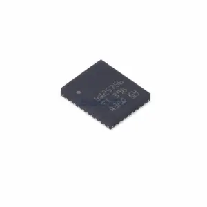
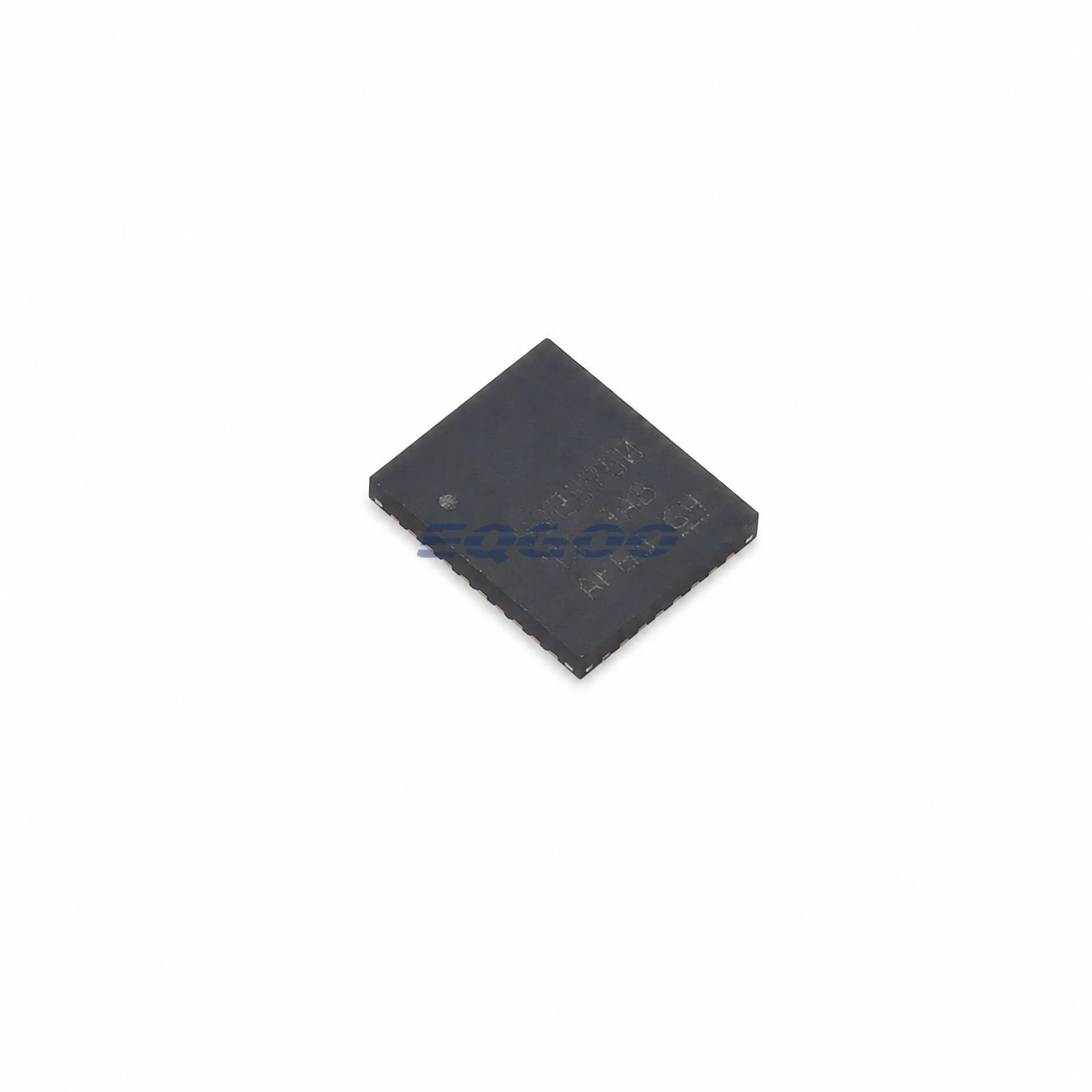
| Exact Package / Packing | VQFN (RRV), 36 pins, 6 mm × 5 mm; 3000-piece large tape and reel |
Product Overview
BQ25750RRVR is a wide-voltage bidirectional battery-charge controller for systems where the adapter voltage and battery voltage can move above or below one another. Its four-switch buck-boost power stage can charge a battery across a 4.2 V to 70 V input range and can reverse power flow from the battery when the system requires a regulated reverse-mode output. The controller drives external N-channel MOSFETs rather than integrating the high-current switching stage.
The supported battery range extends to 70 V, including 1- to 14-cell Li-Ion and 1- to 16-cell LiFePO4 charge profiles. Cell count alone is not the configuration mechanism: charge voltage/current, input-current regulation, protection limits, operating modes, and monitoring are programmed through I²C and/or the available hardware programming inputs. The external battery-voltage feedback and power components still have to be designed for the exact pack.
BQ25750 also separates direct system power from battery conversion. With a valid adapter, the input path can feed the system through the power-path FETs while the buck-boost stage manages battery charging. When the input source falls outside the programmed operating window, the battery path can supply the system. This reduces unnecessary conversion loss compared with routing all system power through the charger converter.
For other charger and bidirectional power-management devices, see HKEQGOO’s Battery Chargers category.
Technical Specifications
| Parameter | Verified Information |
|---|---|
| Manufacturer | Texas Instruments |
| Exact MPN | BQ25750RRVR |
| Topology | Bidirectional synchronous buck-boost controller with external NFET drivers |
| Input Voltage | 4.2 V to 70 V recommended |
| Battery Voltage | 0 V to 70 V recommended |
| Li-Ion Cell Support | 1 to 14 cells |
| LiFePO4 Cell Support | 1 to 16 cells |
| Switching Frequency | 200 kHz to 600 kHz adjustable |
| Charge-Voltage Accuracy | ±0.5% stated feature |
| Charge-Current Accuracy | ±3% stated feature |
| Input-Current Accuracy | ±3% stated feature |
| Reverse-Mode VAC Regulation | 3.3 V to 65 V adjustable, 20 mV per step stated feature |
| Reverse/Input Current Regulation | 400 mA to 20 A with 5 mΩ RAC_SNS under the stated feature conditions |
| Monitoring | Integrated 16-bit ADC for voltage, current, and temperature monitoring |
| Hardware Current Programming | ICHG and ILIM_HIZ resistor options can impose hardware limits; register control remains available |
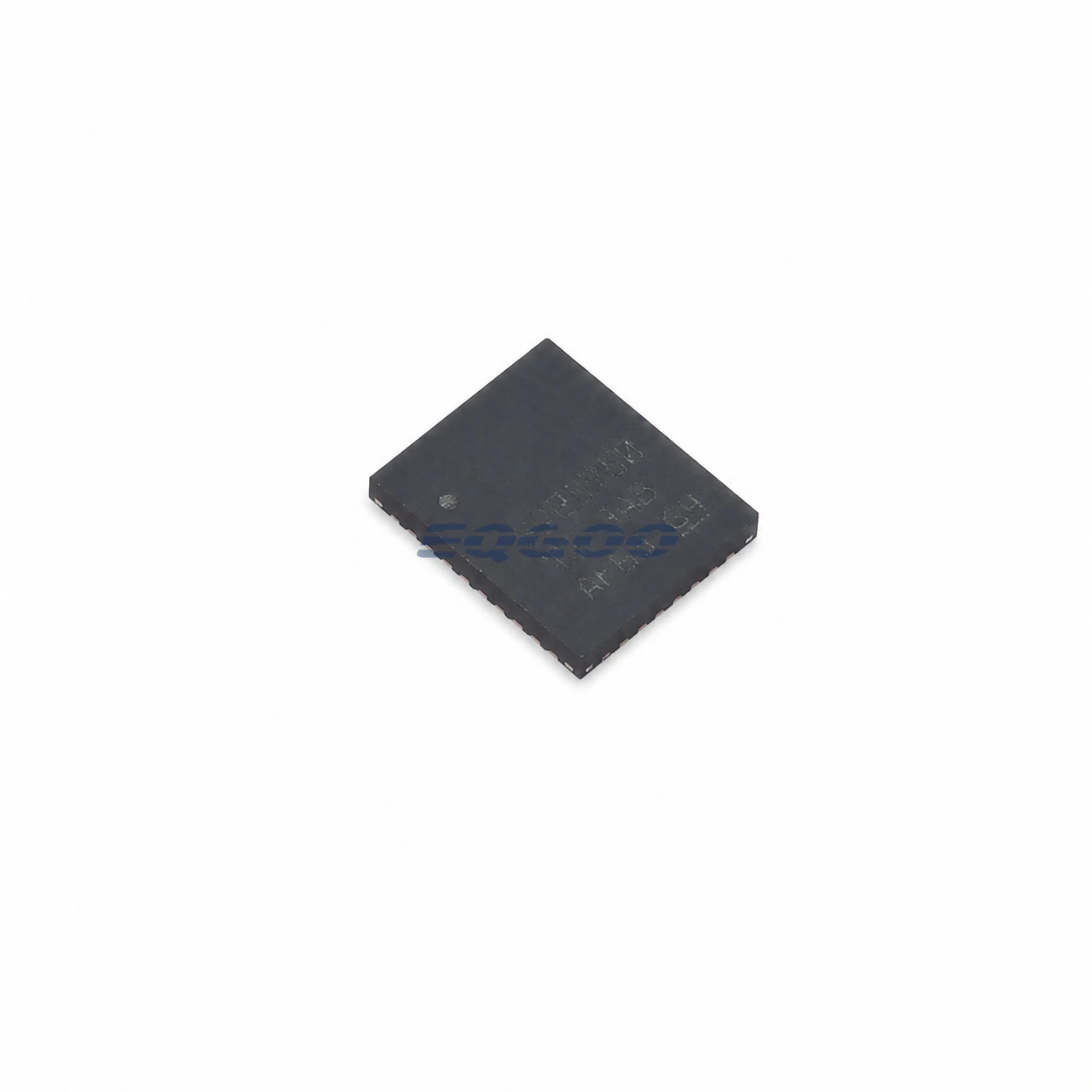
| Package | VQFN (RRV), 36 pins, 6 mm × 5 mm |
| Manufacturer Status | Active / Production |
| Part Marking | BQ25750 |
Functional Highlights
Buck-boost operation removes the requirement that adapter voltage always exceed battery voltage
A conventional buck-only charger requires useful input headroom above the battery. BQ25750 instead uses a four-switch buck-boost stage, allowing regulation when the adapter is above, near, or below the battery voltage within the supported operating range.
This is important for high-cell-count packs and wide-range supplies because the converter can cross between buck and boost operation as voltages change. The inductor, four external switching MOSFETs, current-sense resistors, and gate-drive supply must be selected for the worst voltage/current condition across both operating regions rather than optimized around one fixed conversion ratio.
Reverse mode turns the battery charger into a controlled bidirectional power stage
In reverse operation, energy flows from the battery toward the system/input side and the controller regulates the reverse-mode voltage/current targets. TI positions this capability for USB-PD Extended Power Range and other bidirectional applications, with programmable VAC regulation up to 65 V and current regulation scaling to 20 A with a 5 mΩ input-current sense resistor.
Those current and voltage ranges are controller capabilities, not guaranteed power from the IC package itself. Practical bidirectional power is set by the external MOSFETs, inductor, current-sense elements, connector path, switching frequency, cooling, and PCB copper as well as the programmed protection limits.
Hardware current limits and I²C limits need an intentional hierarchy
BQ25750 provides resistor-programmable ICHG and ILIM_HIZ functions in addition to register-based charge- and input-current control. TI notes that pulling the programming resistor input to ground disables the corresponding hardware current limit, leaving the register setting to control the active current target.
The design should decide whether hardware limits are intended as an independent ceiling or whether the host owns the full range. Treating the resistor network and I²C registers as unrelated settings can create a system that never reaches the requested current or, conversely, removes an expected hardware safeguard.
Design Considerations
- Design the external four-switch stage for both power directions. MOSFET voltage rating, RDS(on), switching loss, body-diode behavior, inductor saturation, sense-resistor dissipation, and thermal paths must be checked in forward charging and reverse operation.
- Program the ACUV/ACOV operating window for the actual source. If VAC falls below or rises above the programmed valid-input window, the controller stops conversion and changes the active power path; these thresholds are system-power decisions, not just fault flags.
- Keep current-sense resistor values consistent with the intended register range. The published current ranges depend on the sense-resistor scaling used in the datasheet; changing RAC_SNS or RBAT_SNS changes current-to-register relationships and loss.
- Coordinate hardware and software limits. ICHG/ILIM_HIZ resistors can constrain current below the host-programmed value; grounding the programming input disables that hardware limit rather than selecting a zero-current target.
- Treat high-current figures as complete-system limits. The controller can support high-current designs, but external FETs, inductor, capacitors, PCB copper, thermal design, and connectors determine whether the finished product can safely deliver them.
Product Status and Exact Order Code
Manufacturer status: Active / Production
Texas Instruments lists BQ25750RRVR in the 36-pin VQFN RRV package with a 3000-piece large tape-and-reel carrier, Level-1-260C-UNLIM MSL classification, an operating-temperature listing of −40°C to +125°C, and part marking BQ25750.
Related Engineering Resources
Quality & Verification Support
Third-party inspection or testing can be arranged according to customer requirements. Testing fees are borne by the buyer. Additional verification requirements can be discussed before shipment. After an order is placed, physical product, label, packaging, and Date Code photos may be provided where appropriate.
Request a Quote
To request a quotation, provide the manufacturer part number, required quantity, destination, target Date Code if applicable, and any testing or inspection requirements.