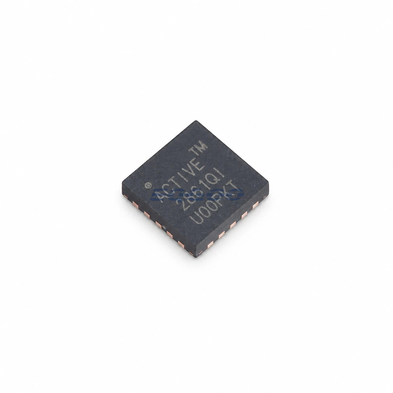
Device Overview
ACT2861QI401-T is a Qorvo 4-switch buck-boost battery charger with integrated MOSFETs for 2- to 5-cell lithium-ion battery systems. The charger accepts a 3.9 V to 29 V input range and supports OTG operation, while configuration and monitoring are handled through an I2C interface.
The combination of buck-boost conversion and multi-cell support is the main selection point for this exact device: the input source may sit above, below, or near the battery-side voltage during operation, so the topology is materially different from a buck-only or boost-only charger.
Selection-Critical Specifications
| Parameter | Confirmed Information | Conditions / Notes |
|---|---|---|
| Charger topology | 4-switch buck-boost charger with integrated MOSFETs | Exact device function |
| Input voltage | 3.9 V to 29 V | General-description operating range |
| Battery support | 2 to 5 lithium-ion cells | Exact charger configuration |
| Switching frequency | 125 / 250 / 500 / 1000 kHz | Programmable frequency options |
| Digital control | I2C | Configuration and monitoring |
| OTG support | Supported | Datasheet states 5 V to 22.5 V input for OTG function |
| Programmable LDO | 2 V to 5.1 V / 100 mA | Auxiliary output LDO |
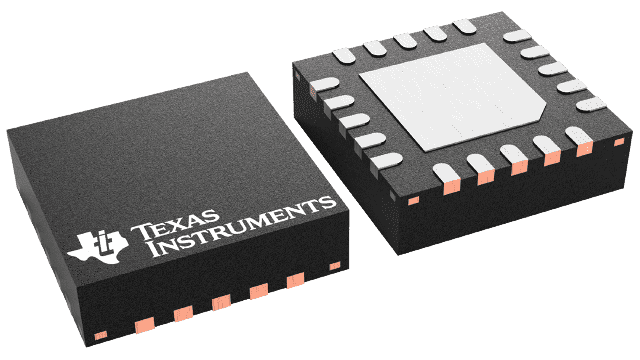
| Package | FCQFN-32, 4 x 4 mm | Exact orderable variant |
Engineering Selection Notes
The 3.9 V to 29 V input span should be checked against the intended 2- to 5-cell battery stack before comparing this part with other charger ICs. The programmable switching-frequency choices also matter at board level because they define a real design option rather than a fixed-frequency operating point.
I2C control is another exact-part consideration: charging configuration and monitoring are digitally accessible, while OTG operation adds a reverse-power operating mode that is not present on every multi-cell charger. The auxiliary 2 V to 5.1 V, 100 mA LDO should be treated as a separate low-current rail rather than as the main battery-charge output.
The 32-lead 4 x 4 mm FCQFN package is a separate board-footprint and assembly constraint, so package compatibility should be checked independently of charger topology or voltage range.
For charge-current sizing, use the datasheet electrical-characteristics tables together with the intended sense-resistor and configuration settings; this page does not state a numeric fast-charge-current limit.