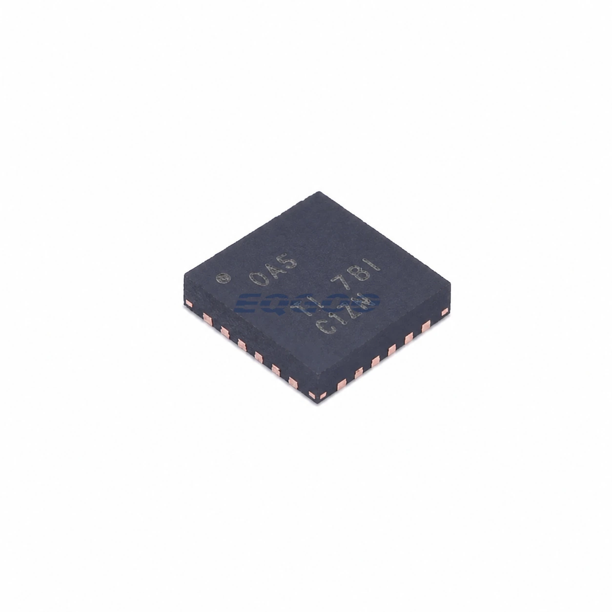

Key Selection Information
| Selection Parameter | Confirmed Information |
|---|---|
| Charger Type | Stand-alone synchronous buck battery-charger controller |
| Battery Configuration | 1 to 6 cells for BQ24610 |
| VCC Operating Range | 5 V to 28 V |
| Switching Frequency | 600 kHz |
| Charge / Adapter Current Capability | Up to 10 A with suitable external power stage and sense components |
| Regulation Accuracy | ±0.5% charge voltage; ±3% charge current; ±3% adapter current |
| Power Management | Adapter-current DPM and automatic adapter/battery system-power selection |
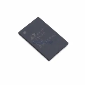
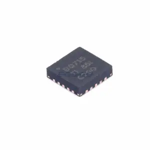
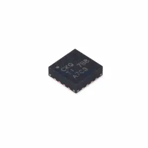
| Exact Package / Packing | VQFN (RGE), 24 pins, 4 mm × 4 mm; 3000-piece large tape and reel |
Product Overview
BQ24610RGER is a stand-alone switched-mode battery-charger controller for higher-power battery systems that need more current or more series cells than a small integrated linear charger can support. It operates a 600 kHz synchronous buck stage using external high-side and low-side N-channel MOSFETs, supports 1- to 6-cell battery configurations, and accepts a 5 V to 28 V VCC operating range.
The device is a controller rather than a complete integrated power converter. Charge current, adapter-current limit, battery regulation voltage, MOSFET selection, inductor value, current-sense resistors, and PCB power layout are all part of the final charger design. TI states charge and adapter current capability up to 10 A, but reaching that level depends on the external sense resistor, FETs, inductor, cooling, and board losses rather than the IC alone.
BQ24610 also monitors adapter current separately from battery current. Its dynamic power-management loop reduces charging current when system demand pushes adapter current toward the ACSET limit, allowing the adapter to be sized around a controlled input-current budget instead of worst-case system load plus maximum battery charge current at the same time.
For other charger-controller and integrated-charger options, see HKEQGOO’s Battery Chargers category.
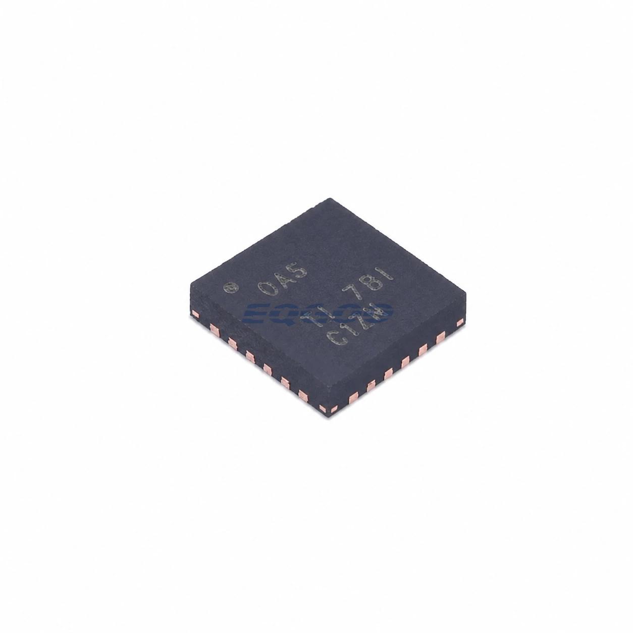
Technical Specifications
| Parameter | Verified Information |
|---|---|
| Manufacturer | Texas Instruments |
| Exact MPN | BQ24610RGER |
| Topology | Synchronous buck charger controller with external NMOS power stage |
| Switching Frequency | 600 kHz |
| BQ24610 Cell Support | 1 to 6 cells |
| VCC Input Operating Range | 5 V to 28 V |
| Maximum Charge / Adapter Current Feature | Up to 10 A with external power components |
| Charge-Voltage Accuracy | ±0.5% stated feature |
| Charge-Current Accuracy | ±3% stated feature |
| Adapter-Current Accuracy | ±3% stated feature |
| Charge-Current Sense | 100 mV full-scale differential between SRP and SRN |
| Adapter-Current Control | External RAC sense resistor and ACSET programming |
| Battery Voltage Programming | External divider to VFB; VFB regulation reference 2.1 V |
| Battery Temperature Input | TS supports thermistor-based hot/cold charge qualification |
| Gate-Drive Supply | 6 V REGN gate-drive supply |
| Package | VQFN (RGE), 24 pins, 4 mm × 4 mm |
| Manufacturer Status | Active / Production |
| Part Marking | OAS |
Functional Highlights
The 10 A figure is a power-stage design capability, not an IC pin-current rating
BQ24610 regulates battery current from the voltage across an external sense resistor and drives external synchronous MOSFETs. TI shows a 100 mV full-scale charge-current sense voltage; with a 10 mΩ sense resistor this corresponds to 10 A. A different sense-resistor value changes the regulated current scale.
The practical maximum therefore depends on conduction loss, MOSFET SOA and RDS(on), inductor saturation current, current-sense dissipation, switching loss, thermal design, and connector/PCB copper capacity. Selecting BQ24610 for a high-current charger requires designing the complete buck stage around the target current rather than treating 10 A as an automatically available output.
Adapter DPM trades battery-charge current for system power
The ACSET loop measures adapter current independently from battery current. If system load increases and total adapter current reaches the programmed input limit, BQ24610 reduces battery charging so the system can remain powered without requiring the adapter to supply both worst-case system current and maximum charge current simultaneously.
This makes ACSET and ISET1 different selection axes. ISET1 defines the desired battery current, while ACSET defines how much current the source is allowed to deliver. Actual battery current is the value the system can support after the load consumes its share of the adapter budget.
External power components determine efficiency and low-current behavior
At higher inductor current, the controller operates synchronously with both external MOSFETs switching. At low current it can enter nonsynchronous/discontinuous operation to prevent negative inductor current. The inductor, FETs, bootstrap network, output capacitance, and current-sense filtering therefore influence efficiency, loop behavior, switching stress, and low-current operation.
Design Considerations
- Choose the charge sense resistor from current range and loss. A larger RSR improves sense signal but dissipates more power; the 100 mV full-scale relationship should be evaluated at maximum charge current.
- Program battery regulation voltage with the VFB divider for the exact pack. The controller supports multiple cell counts because pack voltage is externally set; cell count alone does not configure the correct regulation voltage.
- Coordinate ACSET with the adapter rating and system peak load. If the input-current limit is lower than simultaneous system-plus-charge demand, DPM deliberately reduces charging current.
- Treat external MOSFET and inductor selection as part of charger qualification. The IC supplies gate drive and control, but external-component voltage rating, current rating, loss, and thermal margin determine the finished charger’s capability.
- Solder the exposed thermal pad and use low-impedance power/current-sense routing. TI specifically calls for the thermal pad to be soldered with ground-plane vias for the high-current converter layout.
Product Status and Exact Order Code
Manufacturer status: Active / Production
Texas Instruments lists BQ24610RGER in the 24-pin VQFN RGE package with a 3000-piece large tape-and-reel carrier, Level-2-260C-1 YEAR MSL classification, an operating-temperature listing of −40°C to +85°C, and part marking OAS. BQ24610RGET is the corresponding 250-piece small tape-and-reel option.
Related Engineering Resources
Quality & Verification Support
Third-party inspection or testing can be arranged according to customer requirements. Testing fees are borne by the buyer. Additional verification requirements can be discussed before shipment. After an order is placed, physical product, label, packaging, and Date Code photos may be provided where appropriate.
Request a Quote
To request a quotation, provide the manufacturer part number, required quantity, destination, target Date Code if applicable, and any testing or inspection requirements.