
Key Selection Information
| Selection Parameter | Confirmed Information |
|---|---|
| Battery Configuration | 1-cell or 2-cell Li-Ion / Li-Polymer / LiFePO4 |
| Charger Architecture | 1.2 MHz synchronous buck charger with integrated reverse-blocking and switching MOSFETs |
| Input Operating Range | 4.1 V to 17 V |
| Programmable Battery Voltage | 3.4 V to 9.0 V |
| Fast-Charge Current | Up to 3.0 A |
| Charge Profile | 10% pre-charge and 10% termination relative to fast-charge current |
| Thermal Control | Charge-current thermal regulation at 120°C |
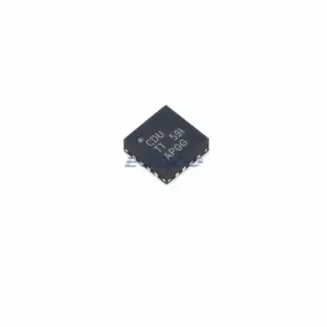
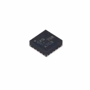
| Exact Package / Packing | WQFN (RTE), 16 pins, 3 mm × 3 mm; 3000-piece large tape and reel |
Product Overview
BQ25306RTER is a highly integrated synchronous buck battery charger for 1S and 2S rechargeable packs. Unlike charger-controller products that require external switching MOSFETs and external current-sense resistors, BQ25306 integrates the reverse-blocking FET, high-side and low-side switching FETs, input/charge current sensing, bootstrap diode, and loop compensation. The remaining power-stage design is therefore centered on the inductor, capacitors, battery-voltage divider, current-programming network, and thermal PCB layout.
The device accepts 4.1 V to 17 V input power and supports a 3.4 V to 9.0 V programmable battery-regulation range. This lets one charger family cover 1S and 2S Li-Ion/Li-Polymer or LiFePO4 designs, but the final charge voltage still comes from the external FB network and must match the exact pack chemistry and series-cell count.
BQ25306 also includes input-voltage dynamic power management. When the source cannot hold the required input voltage under load, VINDPM reduces charging demand instead of continuing to pull the source down. The programmed 3 A maximum is therefore an upper charging target; source voltage, thermal regulation, and the selected battery/input conditions can lower actual current.
For related integrated and controller-based charger options, see HKEQGOO’s Battery Chargers category.
Technical Specifications
| Parameter | Verified Information |
|---|---|
| Manufacturer | Texas Instruments |
| Exact MPN | BQ25306RTER |
| Converter Topology | 1.2 MHz synchronous buck charger |
| Integrated Power Devices | Reverse-blocking FET, high-side switching FET, low-side switching FET |
| Input Voltage | 4.1 V to 17 V recommended |
| Input Absolute Maximum | 28 V at VBUS when converter is not switching |
| Battery Voltage Range | 3.4 V to 9.0 V recommended |
| Maximum Fast-Charge Current | 3.0 A |
| Charge-Voltage Accuracy | ±0.5% stated feature |
| Charge-Current Accuracy | ±10% stated feature |
| Pre-Charge Current | 10% of fast-charge current |
| Termination Current | 10% of fast-charge current |
| Battery Leakage in Hi-Z / Input Removed | 200 nA stated feature at 4.5 V VBAT |
| Thermal Regulation | 120°C charge-current regulation |
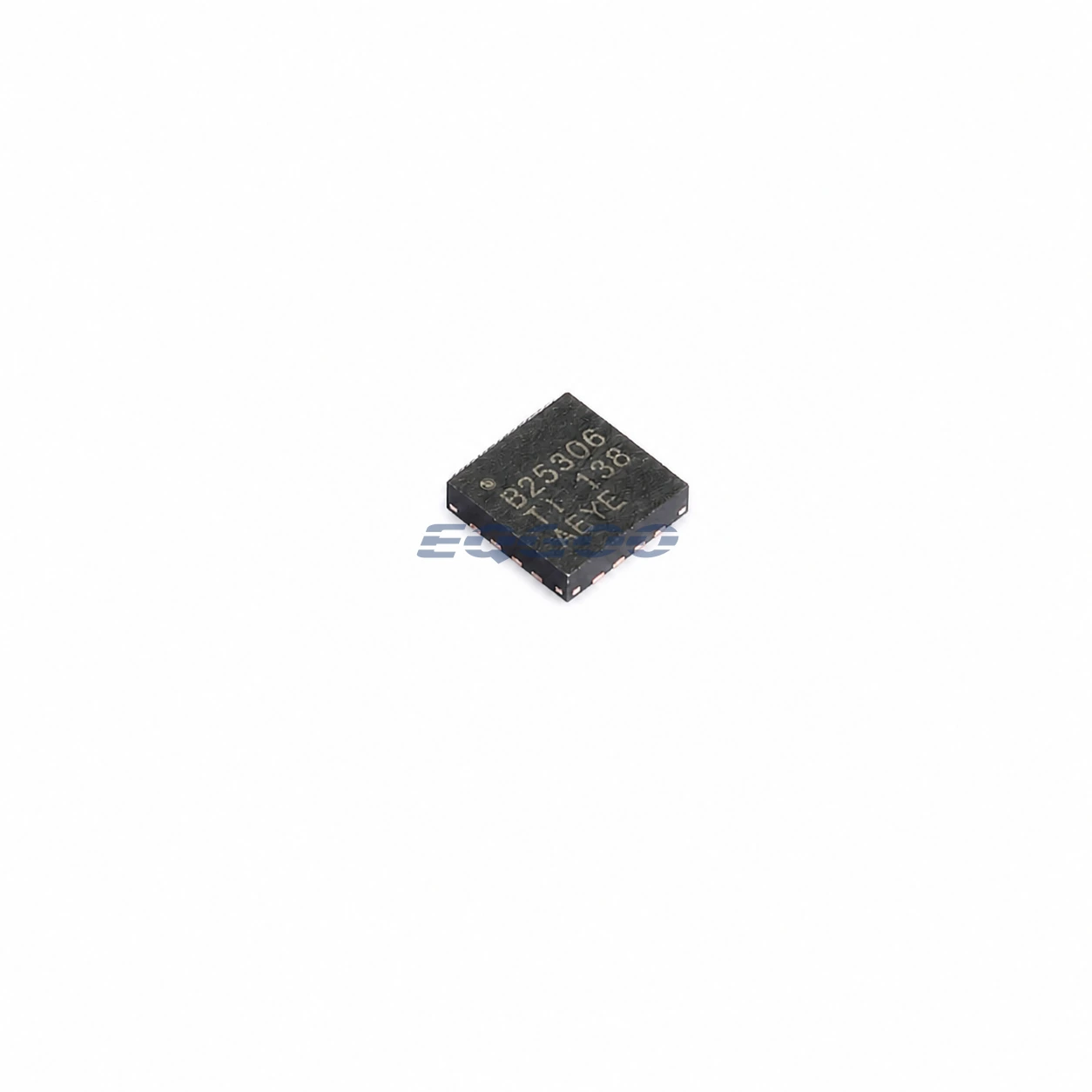
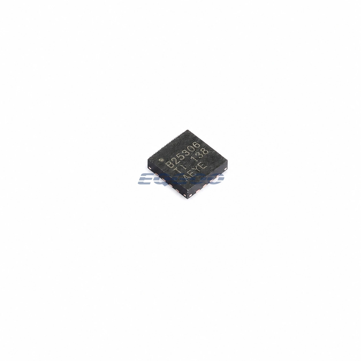
| Package | WQFN (RTE), 16 pins, 3 mm × 3 mm |
| Manufacturer Status | Active / Production |
| Part Marking | B25306 |
Functional Highlights
Integration changes what limits the practical 3 A charge current
BQ25306 integrates the main switching MOSFETs and current sensing, so the designer does not scale the charge current by choosing an external buck-FET pair or current-sense resistor as with a controller-only charger. The practical limit instead moves toward input-source capability, inductor current rating, copper loss, package/board thermal performance, and the charger’s internal current and thermal loops.
TI specifies 120°C charge-current thermal regulation. If board temperature and linear/switching losses push the die toward that point, the charger reduces current even when the external ICHG network requests the 3 A maximum. A 3 A setting should therefore be treated as a programmed ceiling, not a guaranteed current under every input/battery condition.
Input DPM protects a weak source by reducing battery charging
The input-voltage dynamic power-management loop tracks source conditions and reduces charger demand when the input approaches its regulation threshold. This is especially relevant when the same design may use USB-derived sources and higher-voltage adapters with different cable resistance and current capability.
The 17 V recommended input limit and 28 V absolute rating serve different purposes. The wider absolute number is a stress boundary, while charger operation should be designed around the recommended 4.1 V to 17 V range and the source’s ability to remain above the active VINDPM requirement.
Design Considerations
- Program the FB divider for the exact battery pack. The 3.4 V to 9.0 V range enables multiple chemistries and cell counts, but the device does not automatically determine the required full-charge voltage.
- Treat 3 A as a system-level thermal/current target. The inductor, PCB copper, input source, and package thermal path must support the requested current without forcing the 120°C thermal-regulation loop to reduce it.
- Do not expect charge termination while a limiting loop is active. TI states that normal termination requires the charger not to be in input-current DPM or thermal regulation, so source or thermal constraints can change charge-completion timing.
- Keep the high-current buck loop compact. Integrated MOSFETs reduce external component count, but SW, PMID/VBUS, BAT, inductor, and decoupling paths still carry fast switching current and require appropriate placement and grounding.
- Use the 28 V input number only as an absolute-maximum boundary. The normal design range is 4.1 V to 17 V.
Product Status and Exact Order Code
Manufacturer status: Active / Production
Texas Instruments lists BQ25306RTER in the 16-pin WQFN RTE package with a 3000-piece large tape-and-reel carrier, Level-1-260C-UNLIM MSL classification, an operating-temperature listing of −40°C to +85°C, and part marking B25306.
Related Engineering Resources
Quality & Verification Support
Third-party inspection or testing can be arranged according to customer requirements. Testing fees are borne by the buyer. Additional verification requirements can be discussed before shipment. After an order is placed, physical product, label, packaging, and Date Code photos may be provided where appropriate.
Request a Quote
To request a quotation, provide the manufacturer part number, required quantity, destination, target Date Code if applicable, and any testing or inspection requirements.