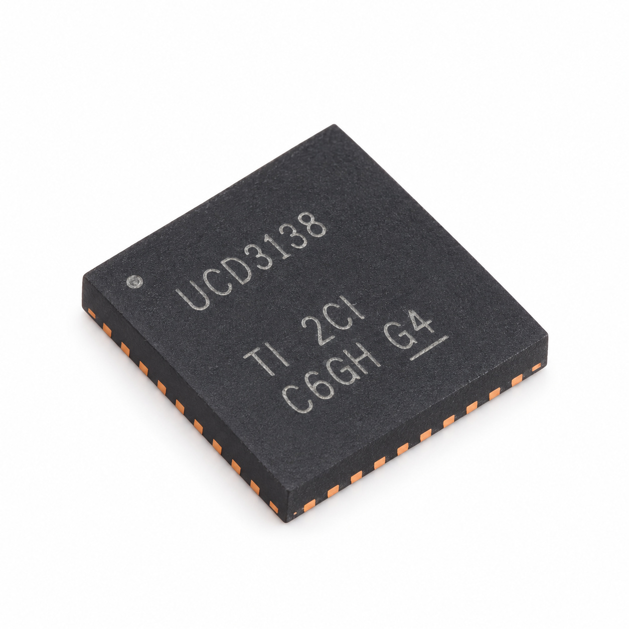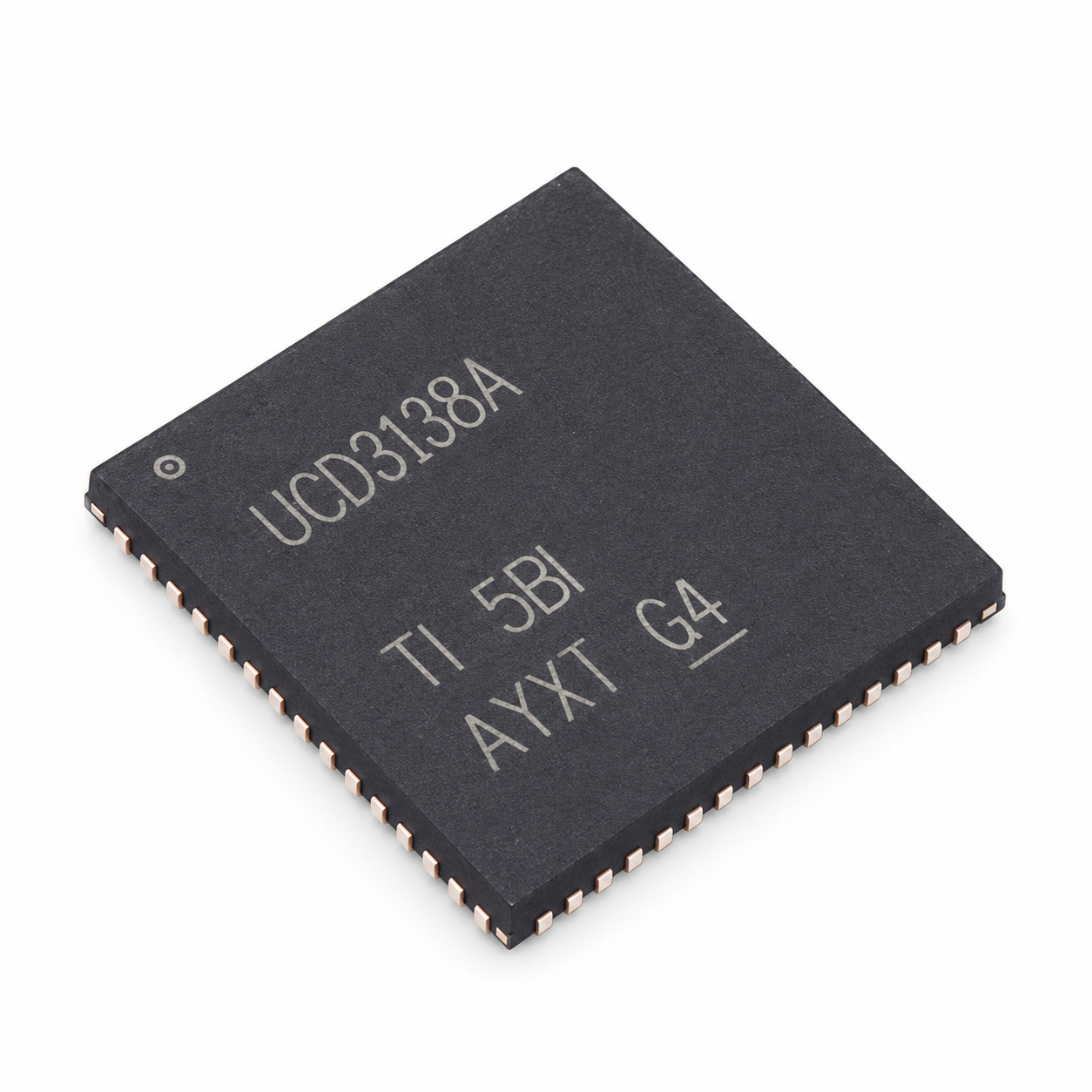
UCD3138ARMHR is Texas Instruments’ UCD3138A programmable digital controller for isolated power-conversion systems, supplied in the RMH 40-pin WQFN, 6 × 6 mm package. It generates digital power-control PWM timing and processes voltage/current feedback; it is not a complete integrated-output buck or isolated power module. The exact RMH ordering code is shipped as 2,000 units per large tape-and-reel according to TI’s package addendum. Those units are the manufacturer’s reel quantity, not the seller’s minimum order.
Technical specifications for the exact 40-pin RMH configuration
| Selection attribute | UCD3138ARMHR | Important manufacturer qualification |
|---|---|---|
| Device role | Programmable digital controller for isolated power | External power stage, sensing, protection and firmware design required |
| Processor | 32-bit ARM7TDMI-S | Processor master clock 31.25 MHz |
| Independent digital control loops | 3 | Verified for exact RMH 40-pin package from TI package resource matrix |
| Digital PWM outputs | 8 | Exact 40-pin RMH resource count; PWM pin routing and configuration still apply |
| DPWM pulse-width resolution | 250 ps | Pulse-width resolution; do not confuse with frequency/phase timing resolution |
| DPWM frequency / phase resolution | 4 ns | Separate from 250 ps pulse-width resolution |
| Switching frequency capability | Up to 2 MHz | DPWM timing capability, not a fixed output switching frequency for every design |
| General-purpose ADC | 12-bit, 7 channels | Exact 40-pin resource matrix; ADC sampling rate 267 ksps |
| Error ADC (EADC) | 16 MHz sample rate | Configurable resolution as fine as 1 mV/LSB in the specified mode |
| Program Flash | 32 KB | Exact RMH 40-pin configuration; do not substitute larger family maxima |
| Data Flash | 2 KB with ECC | Not a generic EEPROM claim |
| Data RAM | 4 KB | Separate from Flash and boot ROM |
| Boot ROM | 4 KB | Supports device boot and field-firmware-loading mechanisms |
| UART | 1 | Exact 40-pin device resource matrix |
| GPIO | 18 | Exact 40-pin matrix; functions can be pin-multiplexed |
| Analog comparators | 6 | Exact package matrix |
| Communication | I²C / PMBus | Manufacturer specifies 100–400 kHz standard/fast-mode timing for this variant |
| Digital supply V33D | 3.0–3.6 V | Recommended operating rail; 3.8 V maximum is absolute stress, not normal supply |
| Analog supply V33A | 3.0–3.6 V | Recommended analog rail, distinct from digital signal return and decoupling |
| V33DIO supply | 3.0–3.6 V | Internally connected to V33D in the 40-pin variant; avoid inferring an independent rail |
| BP18 supply | 1.6–2.0 V | Recommended BP18 range; 2.5 V is the absolute maximum stress value |
| Operating junction temperature | −40 to +125 °C | TJ, not a guaranteed ambient temperature |
| Package RθJA | 31.0 °C/W | TI RMH 40-pin package metric under specified thermal test assumptions |
| Analog supply current | 6.3 mA | V33A with ADC12/EADC sampling disabled, not a universal running total |
| Digital supply during ROM execution | 60 mA | V33D under ROM execution test configuration |
| Digital supply during Flash programming | 70 mA | V33D when programming Flash in ROM mode |
| Total 3.3 V current | 105 mA | TI’s ROM mode with all DPWM outputs at 2 MHz unloaded; not every customer firmware workload |
| Exact manufacturer packing | RMH WQFN-40, 6 × 6 mm; 2,000 large-reel units | Verify land pattern and orderable suffix separately from RHA/VQFN parts |
Use the 40-pin device matrix, not the largest family resource count
The family data sheet presents multiple package configurations. The 40-pin RMH option associated with UCD3138ARMHR has three feedback loops, eight DPWM outputs, seven general-purpose ADC channels, one UART, 18 GPIO resources and 32 KB program Flash. When comparing this part with another UCD3138-family device, those exact counts must be checked against the package/resource matrix rather than copied from a family-wide feature list.
The device’s 250 ps DPWM pulse-width resolution is different from the 4 ns frequency/phase timing resolution. The stated ability to switch at up to 2 MHz is a capability boundary, not a fixed frequency, a guaranteed power-conversion efficiency or a claim about a finished supply. Compensation, firmware, power-stage MOSFETs, sensing, gate drivers and PCB routing remain design-specific.
Keep rail voltages, current tests and thermal limits distinct
Recommended digital and analog power rails V33D and V33A are 3.0–3.6 V. On the 40-pin device, V33DIO is internally connected to V33D; it should not be described as an independently configurable rail. BP18 is specified at 1.6–2.0 V. The 3.8 V (3.3 V rails) and 2.5 V (BP18) absolute maxima are stress limits, not an extended recommended operating window.
For power budgeting, TI’s numbers refer to different workloads and conditions: the 6.3 mA analog-supply figure excludes ADC12/EADC sampling; 60 mA describes V33D during ROM execution; 70 mA is associated with Flash programming; 105 mA is measured in a ROM-mode test with all DPWM channels at 2 MHz unloaded. These values should not be added together as though measured simultaneously, nor presented as the current of every programmed application. Thermal margin depends on actual activity, board heat flow and the recommended −40 to +125 °C junction range.
Selecting the orderable and requesting a quotation
The complete manufacturer orderable UCD3138ARMHR identifies the RMH 40-pin WQFN (6 × 6 mm) and the manufacturer’s 2,000-piece large reel. A similarly named UCD3138RHAR has a different package code and is not established here as a footprint-equivalent or firmware-identical replacement. Check all pin connections, layout dimensions, selected digital-control resources, supply rails and required firmware/PMBus behavior before any substitution.
For purchasing, specify UCD3138ARMHR, the desired quantity and target delivery in your RFQ. Refer to the original Texas Instruments UCD3138A datasheet for electrical test conditions, the RMH pin map and the precise package-resource matrix.