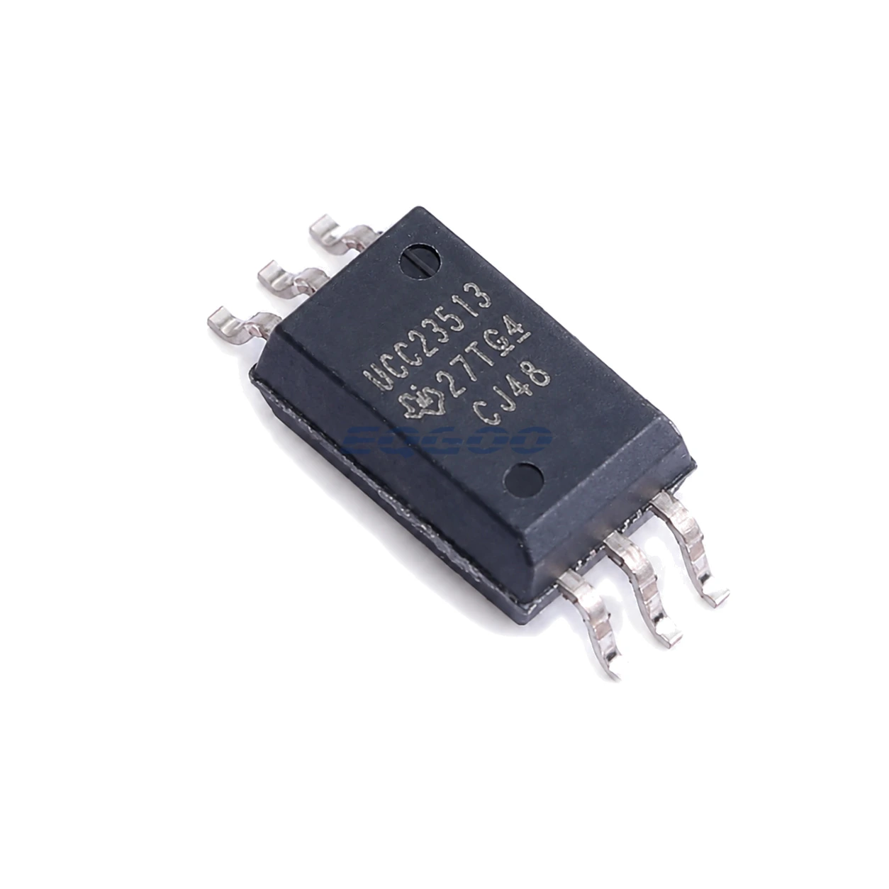

Key Selection Information
| Selection Parameter | Confirmed Information |
|---|---|
| Input Style | Optocoupler-compatible e-diode input |
| Input Current | 7 mA to 16 mA recommended on-current |
| Drive Strength | 4.5 A peak source / 5.3 A peak sink typical |
| Isolation / CMTI | 5.7 kVRMS reinforced; 150 kV/µs minimum CMTI |
| UVLO Variant | Non-B version: 12 V UVLO; 14 V to 33 V recommended VCC−VEE |
| Timing | 105 ns maximum propagation delay |
| Package Isolation Geometry | Stretched SO-6 with >8.5 mm creepage/clearance |
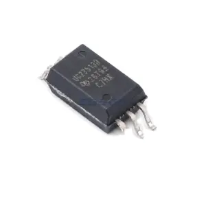
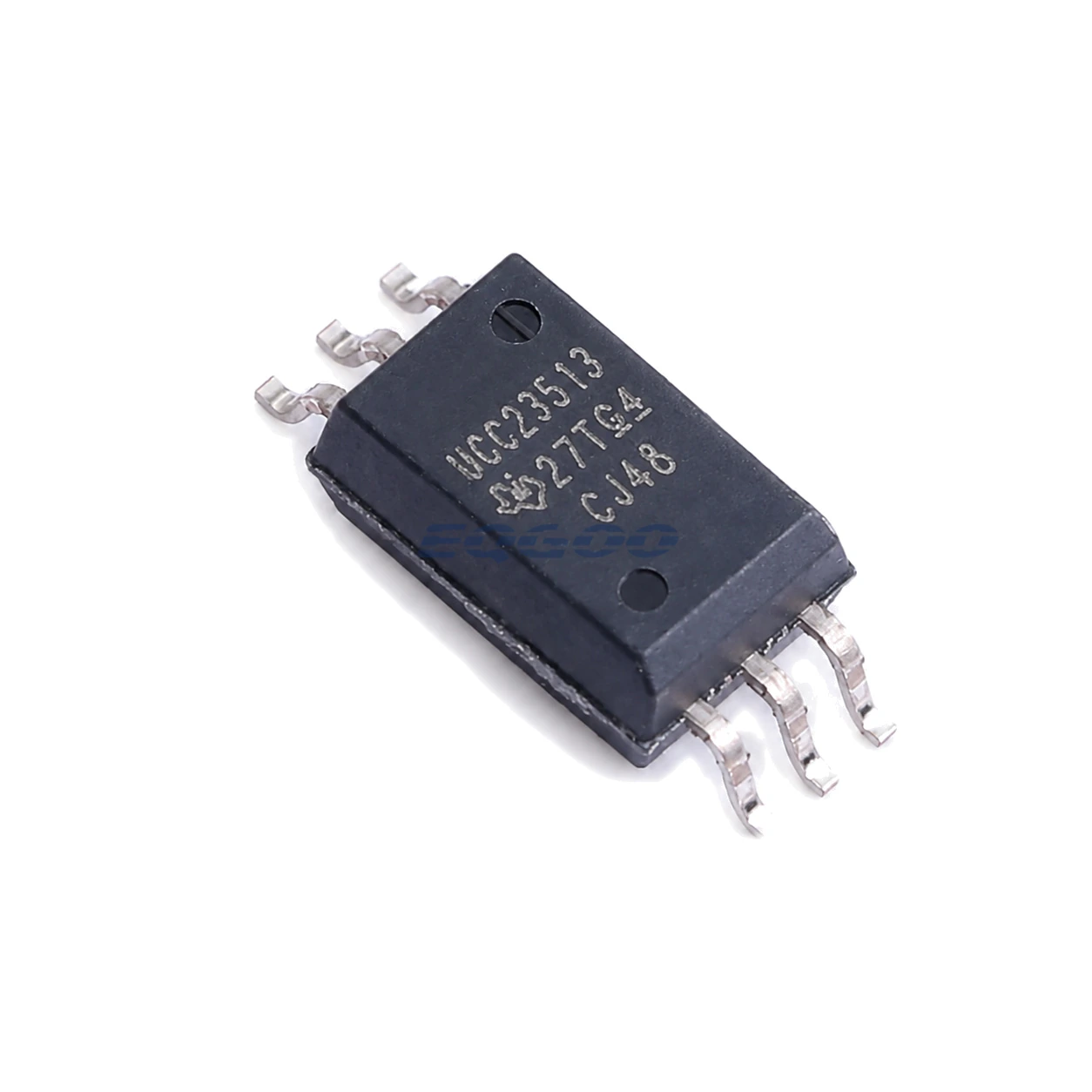
| Exact Packing | SOIC (DWY), 6 pins; 850-piece large tape and reel; marking UCC23513 |
Product Overview
UCC23513DWYR is the 12 V-UVLO version of the UCC23513 opto-compatible isolated gate driver. It uses the same e-diode current-input concept and strong 4.5 A/5.3 A gate drive, but its recommended output-side supply starts at 14 V because of the higher UVLO threshold.
That makes the non-B version a better fit when the power device requires a conventional 15 V-class gate rail and the designer wants more undervoltage margin before allowing turn-on. A system running a lower gate supply should explicitly evaluate the B version instead.
The current-driven e-diode input can retrofit many optocoupler-style control interfaces while improving propagation/CMTI behavior. It still needs a correctly dimensioned external resistor and usually a buffer to source the required forward current.
For related devices, see HKEQGOO’s Isolators – Gate Drivers category.
Technical Specifications
| Parameter | Verified Information |
|---|---|
| Manufacturer | Texas Instruments |
| Exact MPN | UCC23513DWYR |
| Input Style | Optocoupler-compatible e-diode input |
| Input Current | 7 mA to 16 mA recommended on-current |
| Drive Strength | 4.5 A peak source / 5.3 A peak sink typical |
| Isolation / CMTI | 5.7 kVRMS reinforced; 150 kV/µs minimum CMTI |
| UVLO Variant | Non-B version: 12 V UVLO; 14 V to 33 V recommended VCC−VEE |
| Timing | 105 ns maximum propagation delay |
| Package Isolation Geometry | Stretched SO-6 with >8.5 mm creepage/clearance |
| Exact Packing | SOIC (DWY), 6 pins; 850-piece large tape and reel; marking UCC23513 |
| Manufacturer Status | Active / Production |
| Part Marking | UCC23513 |
Functional Highlights
12 V UVLO protects higher-voltage gate-drive rails from weak turn-on
For IGBTs and some SiC configurations, preventing operation during a sagging gate supply can reduce partial-enhancement loss. The actual threshold must still be coordinated with the switch’s gate-voltage requirements.
Pin-compatible intent does not remove input-current design work
The e-diode’s forward current should stay between 7 mA and 16 mA over buffer-voltage, resistor and temperature tolerance. A legacy optocoupler resistor value should be recalculated, not assumed valid.
Design Considerations
- Use the non-B 12 V UVLO variant only when the gate rail remains comfortably above its rising threshold.
- Recalculate input-current resistor values for the UCC23513 e-diode rather than copying an LED optocoupler network.
- Protect creepage/clearance around the stretched SO-6 and keep gate-loop inductance low.
Product Status and Exact Order Code
Manufacturer status: Active / Production
Texas Instruments lists UCC23513DWYR as Active / Production; SOIC (DWY), 6 pins; 850-piece large tape and reel; Level-2-260C-1 YEAR; −40°C to +125°C; marking UCC23513.
Related Engineering Resources
Quality & Verification Support
Third-party inspection or testing can be arranged according to customer requirements. Testing fees are borne by the buyer. Additional verification requirements can be discussed before shipment. After an order is placed, physical product, label, packaging, and Date Code photos may be provided where appropriate.
Request a Quote
To request a quotation, provide the manufacturer part number, required quantity, destination, target Date Code if applicable, and any testing or inspection requirements.