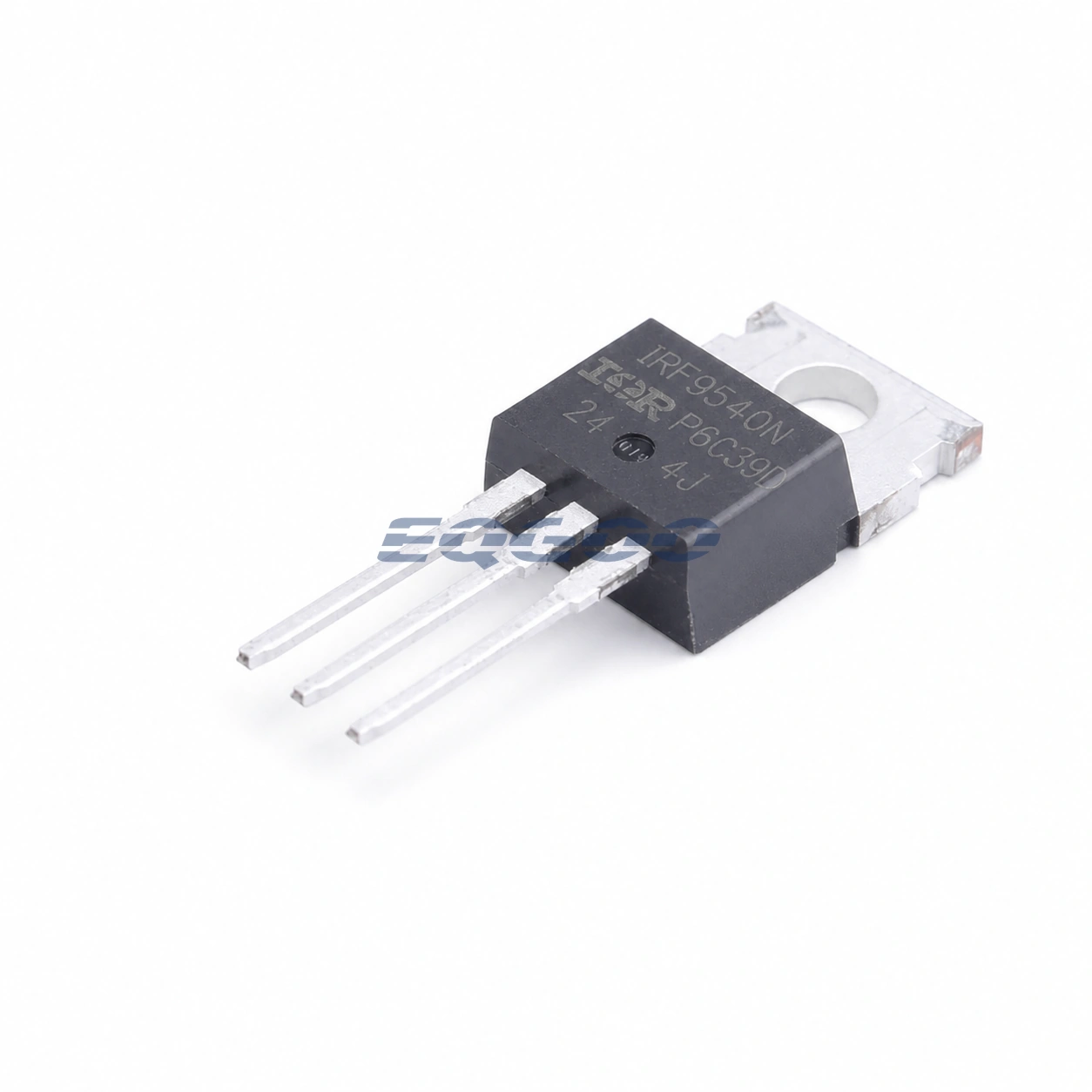
Key Selection Information
| Selection Parameter | Confirmed Information |
|---|---|
| Device type | Single P-channel power MOSFET |
| VDS maximum | -100 V |
| ID maximum at 25°C | -23 A |
| RDS(on) maximum at 10 V | 117 mΩ |
| Typical gate charge at 10 V | 64.7 nC |
| Maximum junction temperature | 175°C |
| Package | TO-220 |
| Product status | Active |
Product Overview
The IRF9540NPBF is the exact active Infineon OPN for a -100 V P-channel power MOSFET in the TO-220 through-hole package. Its P-channel polarity makes it useful for high-side switching arrangements where a simpler gate-drive scheme is preferred over the lower conduction loss usually available from an equivalent N-channel device.
Infineon specifies -23 A maximum drain current at 25°C and 117 mΩ maximum RDS(on) at a -10 V gate drive. Typical total gate charge is 64.7 nC, so the gate driver still needs adequate source and sink capability if the device is switched at meaningful frequency.
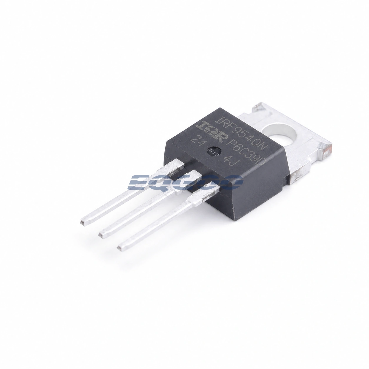
Technical Specifications
| Parameter | Confirmed Information |
|---|---|
| Polarity | P-channel |
| VDS maximum | -100 V |
| ID maximum at 25°C | -23 A |
| RDS(on) maximum at VGS = -10 V | 117 mΩ |
| Typical total gate charge | 64.7 nC |
| Gate-drain charge | 34 nC |
| VGS(th) range | -2 V to -4 V |
| VGS maximum | ±20 V |
| Total power dissipation | 140 W maximum |
| RthJC maximum | 1.1 K/W |
| Maximum junction temperature | 175°C |
| Package | TO-220 |
| Mounting | Through hole |
| Product status | Active |
Design Considerations
The published -23 A drain-current figure is a device rating under controlled thermal conditions, not a guaranteed continuous current on an arbitrary PCB or heatsink. Use the real case temperature, heatsink interface and duty cycle when calculating junction temperature.
This part is not a low-voltage logic-level MOSFET by specification. Its RDS(on) figure is specified at -10 V VGS, so a 5 V or 3.3 V gate-drive system should not assume the same conduction resistance without checking the transfer and on-resistance curves.
Quality & Verification Support
Third-party inspection or testing can be arranged according to customer requirements. Testing fees are borne by the buyer. Additional verification requirements can be discussed before shipment. After an order is placed, physical product, label, packaging, and Date Code photos may be provided where appropriate.
Request a Quote
To request a quotation, provide the manufacturer part number, required quantity, destination, target Date Code if applicable, and any testing or inspection requirements.