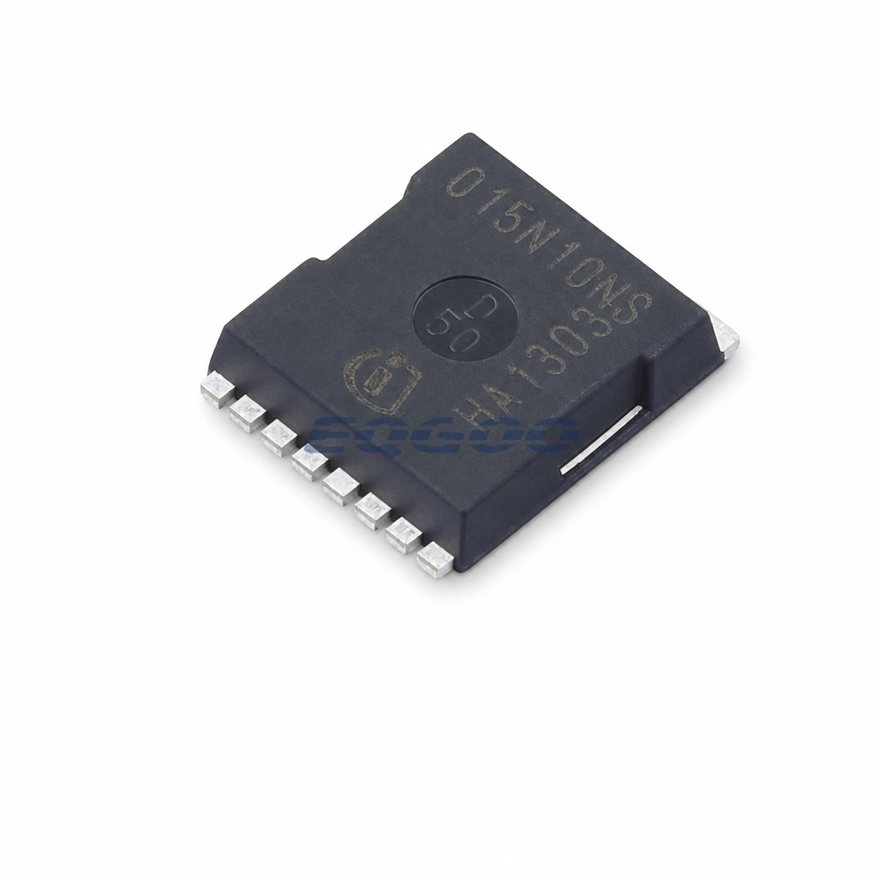
Key Selection Information
| Selection Parameter | Confirmed Information |
|---|---|
| Device type | Single N-channel power MOSFET |
| Technology | StrongIRFET 2 |
| VDS maximum | 100 V |
| ID maximum at 25°C | 315 A |
| RDS(on) maximum at 10 V | 1.5 mΩ |
| Typical gate charge at 10 V | 161 nC |
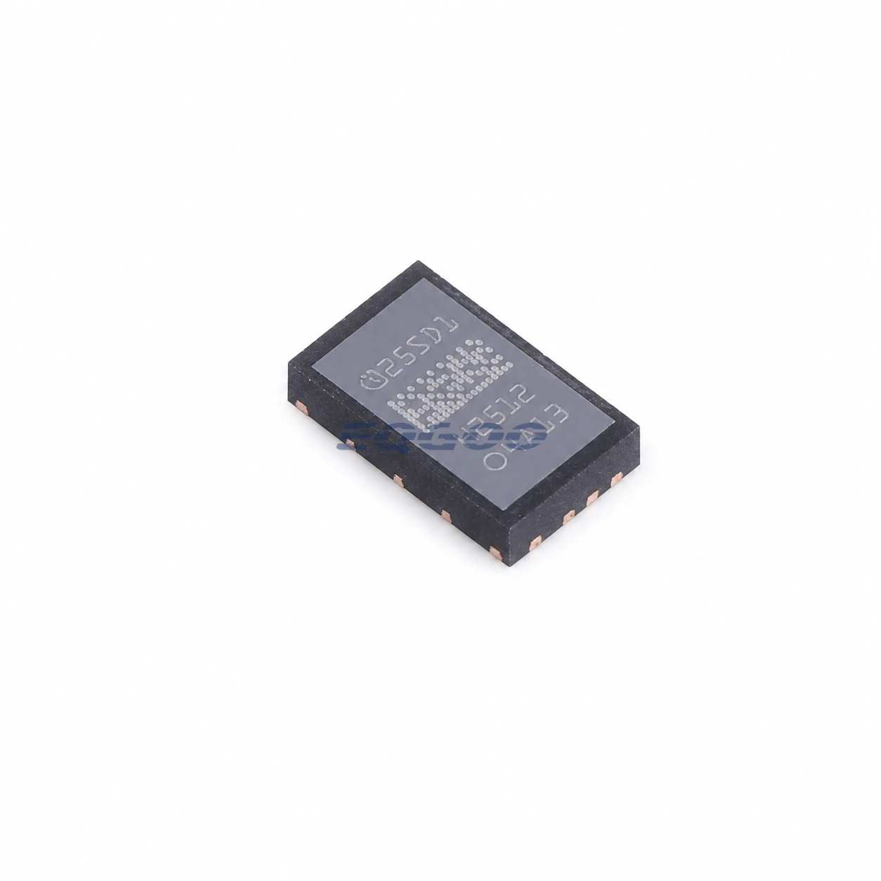
| Package | PG-HSOF-8 / TOLL |
| Product status | Active and preferred |
Product Overview
The IPT015N10NF2SATMA1 is the exact tape-and-reel OPN for Infineon’s StrongIRFET 2 100 V N-channel power MOSFET in the TOLL package. It targets very high-current low-voltage power stages where conduction loss and package current capability are primary selection constraints.
Infineon specifies a maximum 1.5 mΩ RDS(on) at 10 V gate drive, 315 A maximum drain current at 25°C and a 1260 A pulsed-current rating. Those headline current values are device limits rather than board-level guarantees; the TOLL thermal interface, copper area, busbar connection and switching duty determine usable continuous current in a finished converter.
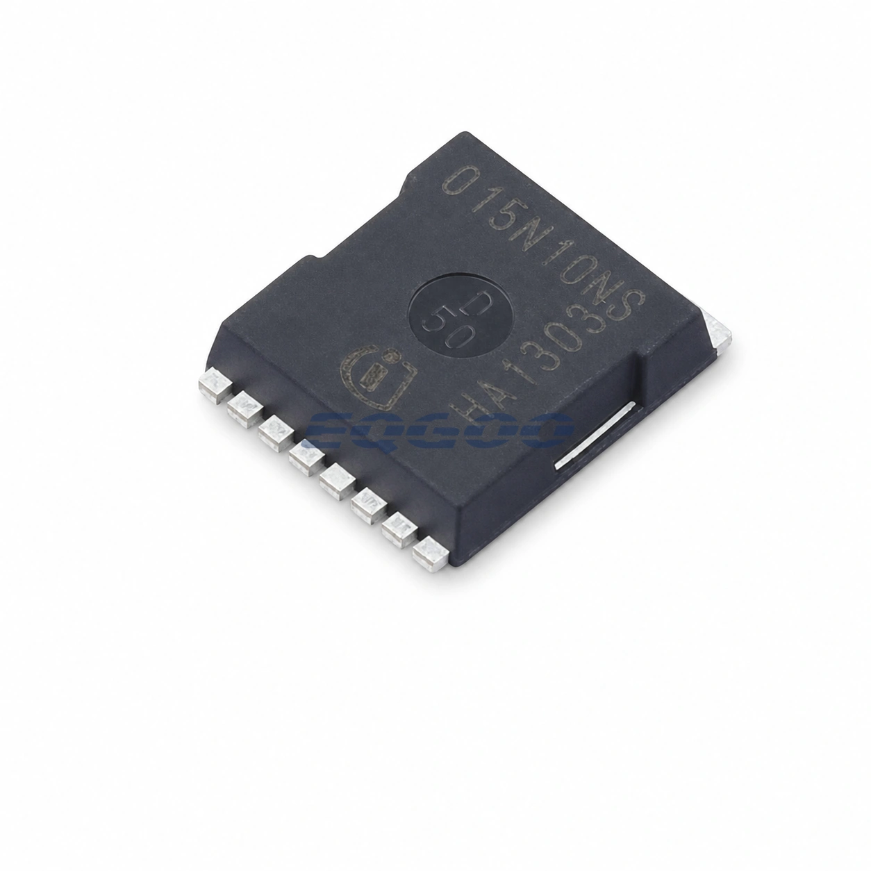
Technical Specifications
| Parameter | Confirmed Information |
|---|---|
| Polarity | N-channel |
| VDS maximum | 100 V |
| ID maximum at 25°C | 315 A |
| Pulsed drain current | 1260 A |
| RDS(on) maximum at VGS = 10 V | 1.5 mΩ |
| Typical total gate charge | 161 nC |
| Power dissipation maximum | 300 W |
| VGS(th) range | 2.2 V to 3.8 V |
| Typical VGS(th) | 3 V |
| Operating temperature | -55°C to +175°C |
| Package | PG-HSOF-8 / TOLL |
| Battery-voltage application class | 48 V to 72 V |
| Product status | Active and preferred |
Design Considerations
The low RDS(on) reduces conduction loss, but 161 nC gate charge makes gate-drive strength and switching frequency important. At high frequency, the driver must charge and discharge the gate fast enough to control switching loss without creating excessive dv/dt, ringing or EMI.
The 100 V rating also needs adequate transient margin in 48–72 V systems. Drain overshoot from package/PCB inductance can consume that margin quickly at hundreds of amperes, so snubbing, decoupling and current-loop layout should be evaluated from measured switching waveforms.
Related Engineering Resources
Quality & Verification Support
Third-party inspection or testing can be arranged according to customer requirements. Testing fees are borne by the buyer. Additional verification requirements can be discussed before shipment. After an order is placed, physical product, label, packaging, and Date Code photos may be provided where appropriate.
Request a Quote
To request a quotation, provide the manufacturer part number, required quantity, destination, target Date Code if applicable, and any testing or inspection requirements.