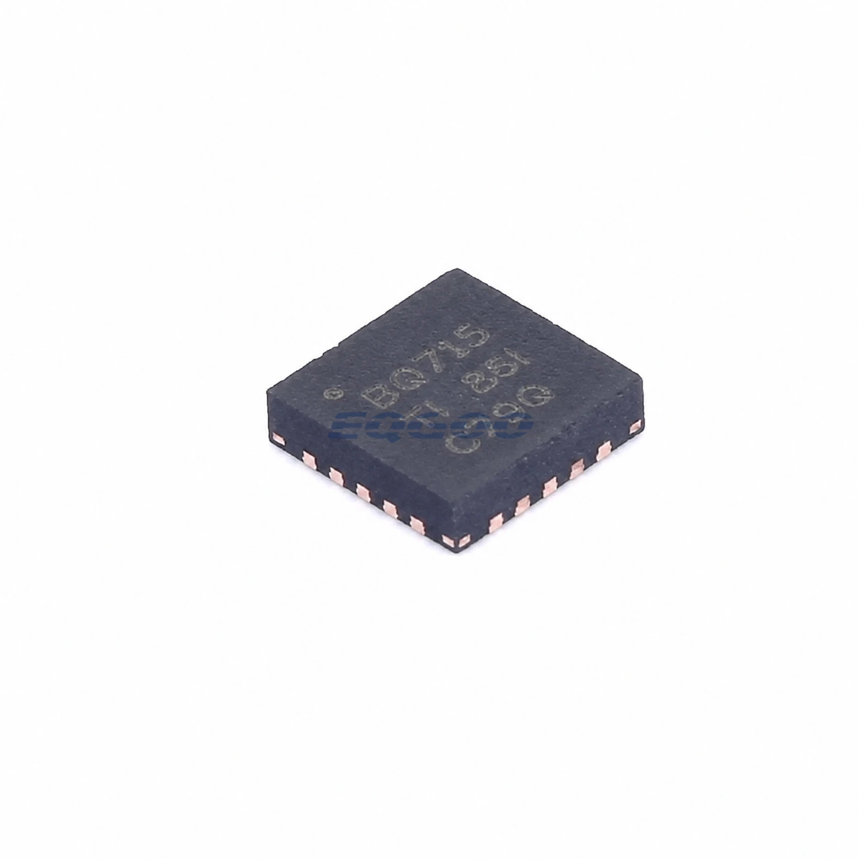

Key Selection Information
| Selection Parameter | Confirmed Information |
|---|---|
| Charger Architecture | NVDC-1 synchronous buck battery-charger controller |
| Battery Configuration | 2-cell or 3-cell Li-Ion |
| Input Range | 6 V to 24 V |
| Host Interface | SMBus-controlled charge voltage, current and minimum system voltage |
| Switching Frequency | Selectable 600 kHz, 800 kHz, or 1 MHz |
| System Behavior | Instant-on operation with absent or deeply discharged battery |
| Power Management | Input-current DPM with battery supplement mode |
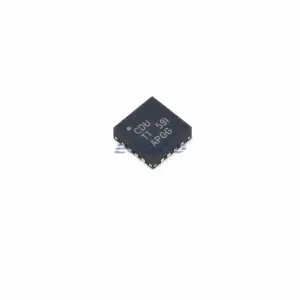
| Exact Package / Packing | VQFN (RGR), 20 pins, 3.5 mm × 3.5 mm; 3000-piece large tape and reel |
Product Overview
BQ24715RGRR is a host-controlled NVDC-1 battery-charger controller for 2S and 3S Li-Ion systems. Rather than fixing the system rail directly to the adapter or battery, the NVDC power path maintains the system node at or above a programmable minimum voltage while the host sets charge voltage, charge current, input-current limit, and related operating parameters through SMBus.
This architecture is useful when the system must start before the battery is ready to supply it. With an absent or deeply discharged battery, the charger can regulate the system node from the adapter while the BATFET operates in a controlled mode. As battery voltage rises, the battery path transitions toward normal conduction. The minimum-system-voltage setting is therefore a system-power parameter, not just a charging parameter.
BQ24715 also uses input-current dynamic power management. When adapter current reaches the programmed limit, battery charge current is reduced so the system load receives priority. If system demand continues increasing after charge current reaches zero, the battery can supplement the system through the BATFET path.
For related charger-controller options, see HKEQGOO’s Battery Chargers category.
Technical Specifications
| Parameter | Verified Information |
|---|---|
| Manufacturer | Texas Instruments |
| Exact MPN | BQ24715RGRR |
| Battery Support | 2S / 3S Li-Ion |
| Input Operating Range | 6 V to 24 V |
| Power-Path Type | NVDC-1 with external ACFET/RBFET and BATFET control |
| Charge-Voltage Programming | 11-bit SMBus setting, 16 mV per step |
| Input / Charge-Current Programming | 7-bit SMBus setting, 64 mA per step |
| Minimum-System-Voltage Programming | 6-bit SMBus setting |
| Switching Frequency | 600 kHz / 800 kHz / 1 MHz selectable |
| Charge-Voltage Accuracy | ±0.5% stated feature |
| Input / Charge-Current Accuracy | ±3% stated feature |
| Current Monitor Accuracy | ±2% stated for 40× input / 16× discharge-current monitor output |
| Quiescent Current | 500 µA stated feature |
| External Power Stage | High-side / low-side N-channel MOSFETs plus external inductor and sense resistors |
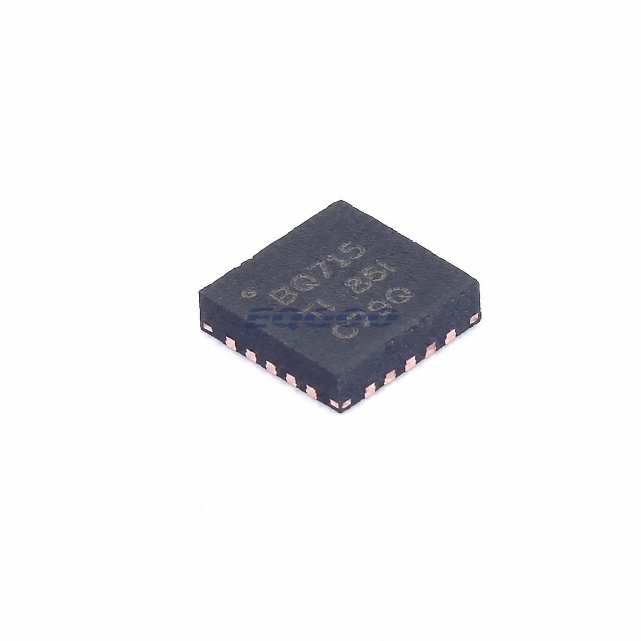
| Package | VQFN (RGR), 20 pins, 3.5 mm × 3.5 mm |
| Manufacturer Status | Active / Production |
| Part Marking | BQ715 |
Functional Highlights
Minimum system voltage supports instant-on operation before the battery is ready
When the battery is below the programmed minimum system voltage, BQ24715 can operate the BATFET in a controlled linear mode so the adapter powers the system while battery conditions are still poor. The host therefore does not need to wait for a deeply discharged pack to recover before bringing up the system rail.
The minimum-system setting must match the downstream load’s actual voltage requirement. Setting it too low can leave the system below its intended operating threshold, while setting it unnecessarily high increases the converter output requirement during pre-charge or no-battery operation.
Input-current DPM makes system load the priority load
With DPM enabled, BQ24715 monitors adapter current against the host-programmed input-current limit. As system current rises, the charger reduces battery current linearly. Once charge current reaches zero, further load demand can move the battery into supplement operation.
This means ChargeCurrent and input-current-limit settings should not be treated as independent maximums that are always available simultaneously. The source budget is shared, and charging is intentionally reduced to protect the adapter limit while maintaining system operation.
SMBus settings are part of the power design, not only configuration metadata
Charge voltage, charge current, input-current limit, minimum system voltage, switching frequency, and operating modes are controlled through registers. After power-up, the converter initially follows its hardware/default state, including CELL-pin behavior, until host programming establishes the intended operating point.
Firmware initialization and fault recovery therefore belong in the charger design review. A valid schematic alone does not guarantee the required pack voltage and current settings if the host does not program and maintain the correct registers.
Design Considerations
- Select the CELL configuration and SMBus voltage settings for the same pack. The hardware cell configuration defines startup behavior; the host’s programmed charge voltage must remain consistent with the intended 2S or 3S battery.
- Budget adapter current against peak system demand. DPM reduces charging as system load approaches the input-current limit, so charge-time estimates should include realistic system consumption rather than only the programmed battery current.
- Design the external buck stage around the selected switching frequency. Moving from 600 kHz to 1 MHz can reduce passive size but changes switching loss, inductor requirements, thermal performance, and EMI behavior.
- Control adapter-FET inrush. TI specifically discusses ACFET gate capacitance and the ACDRV/CMSRC network because turn-on speed affects adapter inrush and power-path startup.
- Use low-impedance current-sense and PowerPAD layout. Charge/input-current accuracy depends on the external sense network, and the exposed pad must be soldered into the grounding/thermal layout.
Product Status and Exact Order Code
Manufacturer status: Active / Production
Texas Instruments lists BQ24715RGRR in the 20-pin VQFN RGR package with a 3000-piece large tape-and-reel carrier, Level-2-260C-1 YEAR MSL classification, an operating-temperature listing of −20°C to +125°C, and part marking BQ715. BQ24715RGRT is the corresponding 250-piece small tape-and-reel option.
Related Engineering Resources
Quality & Verification Support
Third-party inspection or testing can be arranged according to customer requirements. Testing fees are borne by the buyer. Additional verification requirements can be discussed before shipment. After an order is placed, physical product, label, packaging, and Date Code photos may be provided where appropriate.
Request a Quote
To request a quotation, provide the manufacturer part number, required quantity, destination, target Date Code if applicable, and any testing or inspection requirements.