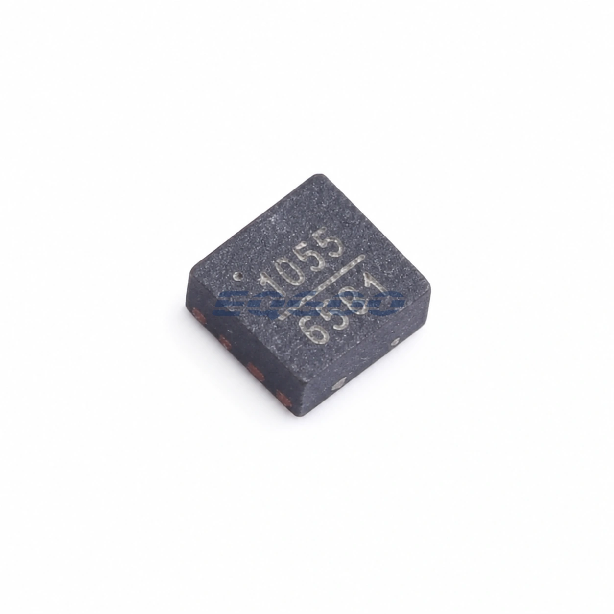
Key Selection Information
| Selection Parameter | Confirmed Information |
|---|---|
| Switch type | GaAs SPST RF switch |
| Frequency range | 0.5 GHz to 4.0 GHz |
| Insertion loss | 0.7 dB typical at 2.0 GHz |
| Input IP3 | >60 dBm typical |
| Control | Single positive control, 0 V or 3 V |
| Off-state RF1 | Reflective open |
| Off-state RF2 | 50 Ω terminated |
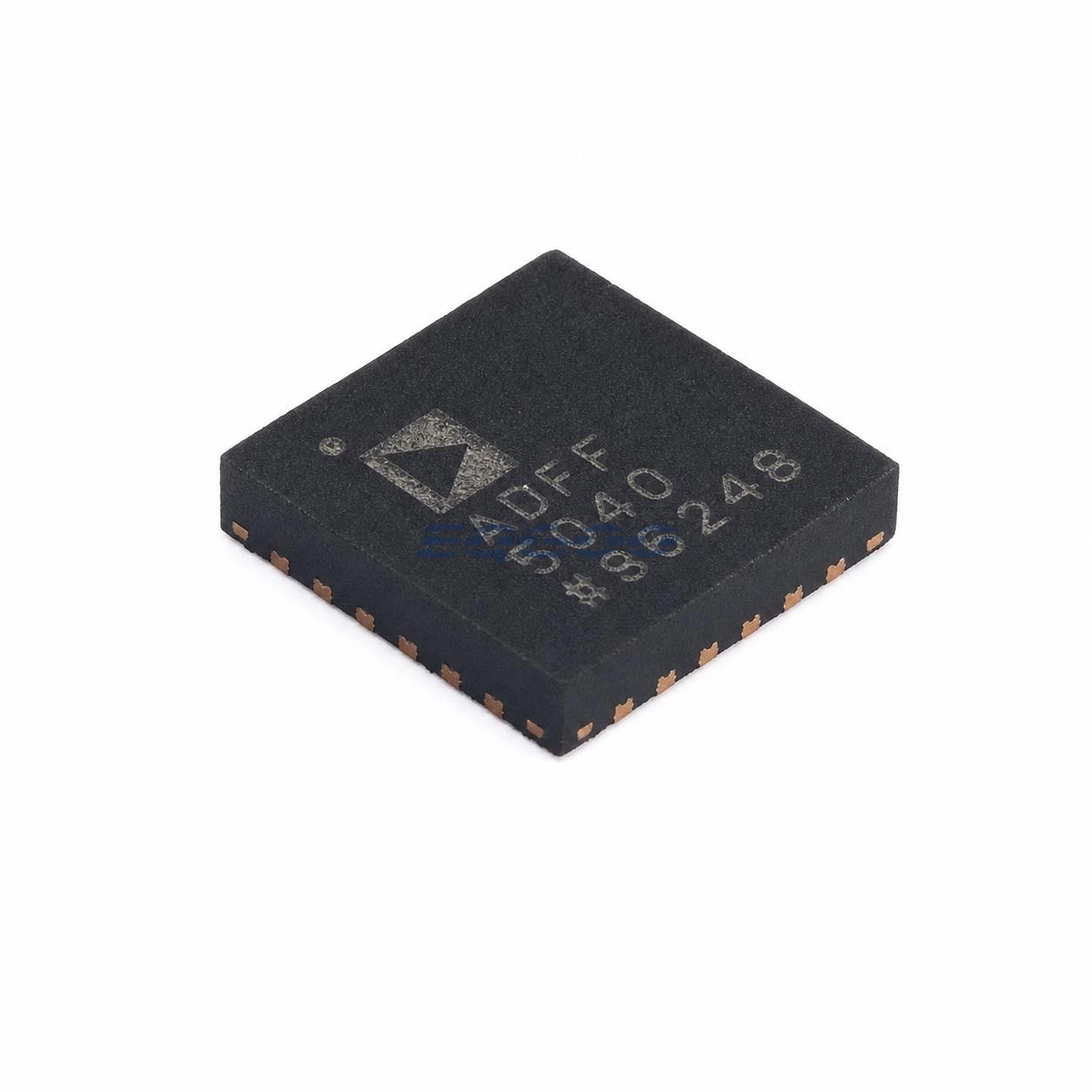
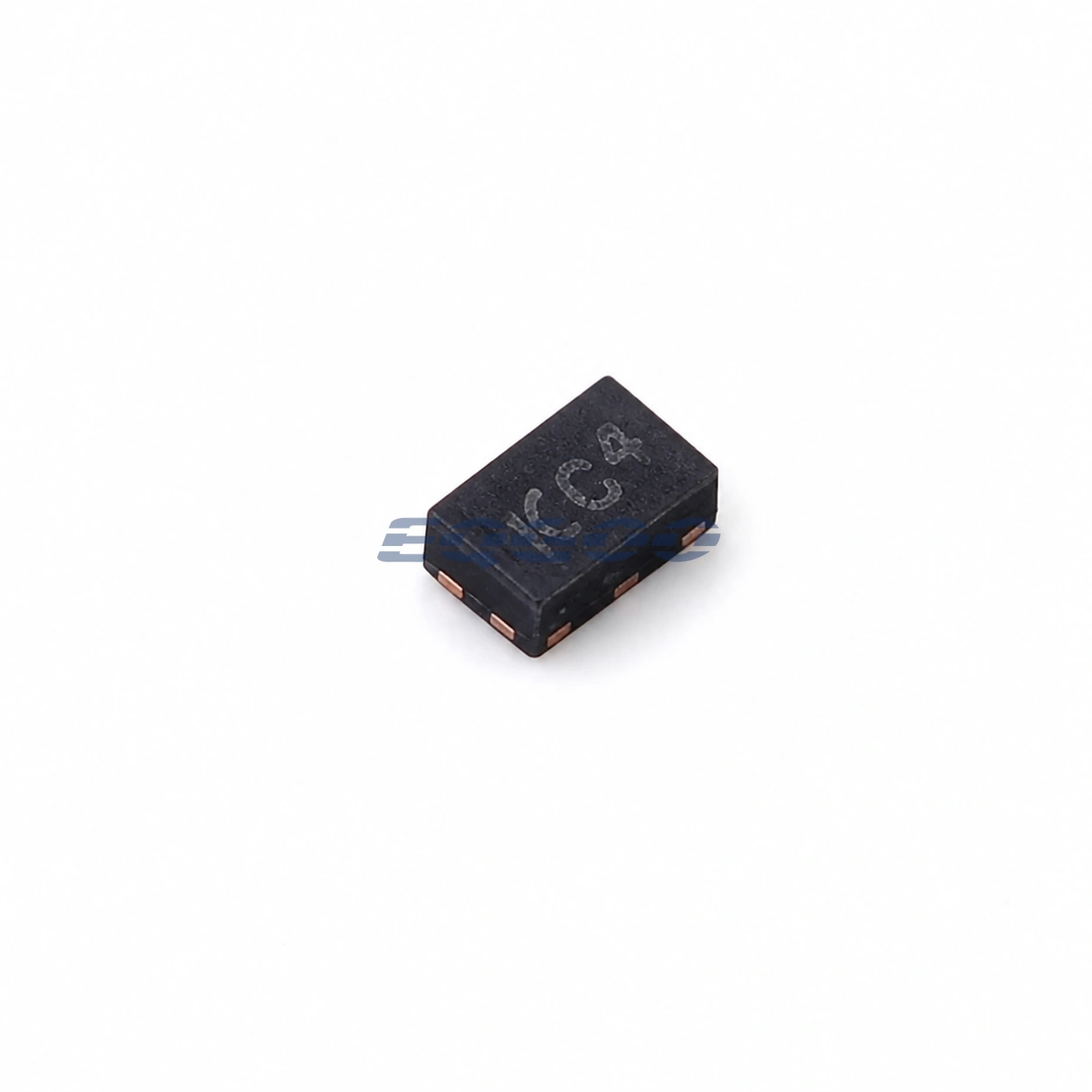
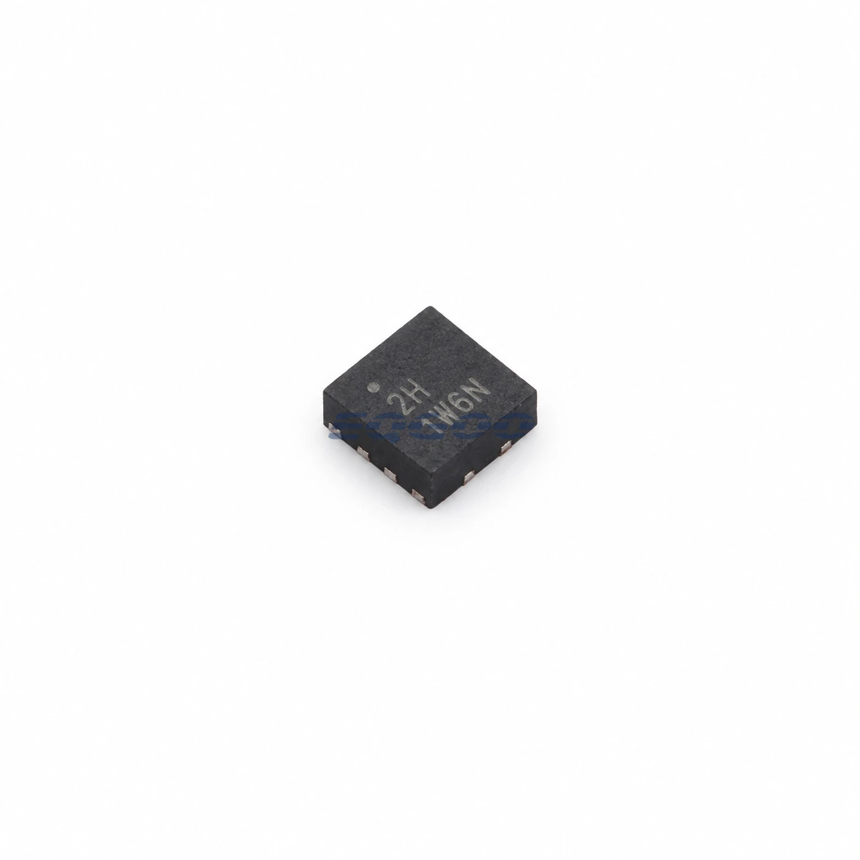
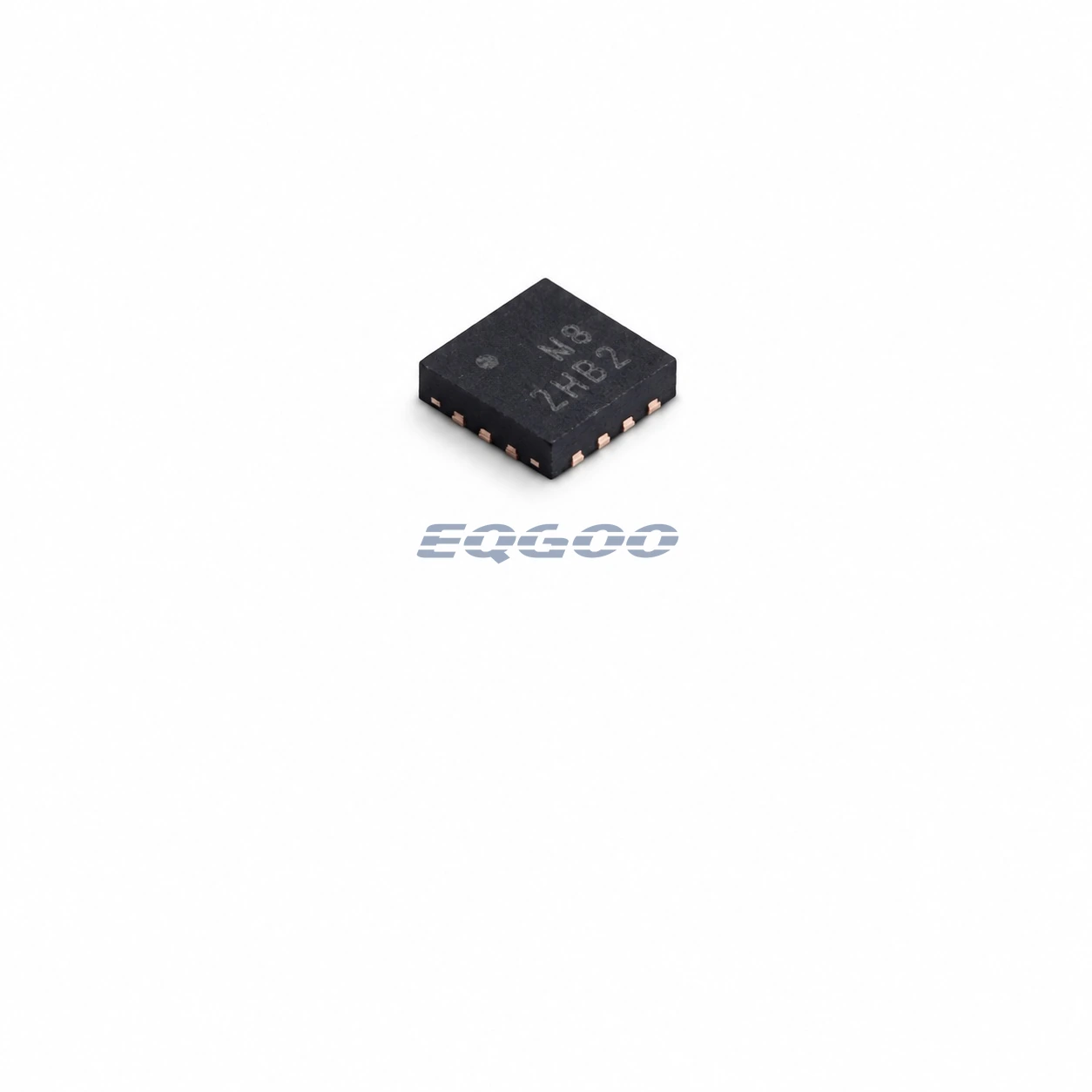
| Package | 8-lead LFCSP, 2 × 2 mm with exposed pad |
Product Overview
The HMC1055LP2CETR is the tape-and-reel orderable version of Analog Devices’ HMC1055 GaAs SPST RF switch. It covers 0.5 GHz to 4.0 GHz and combines 0.7 dB typical insertion loss at 2 GHz with greater than 60 dBm typical input IP3, making linearity a major selection advantage.
The off-state topology is not symmetric. RF1 becomes a reflective open while RF2 is internally terminated to 50 Ω. That behavior matters when deciding which side of the switch faces a sensitive source, filter, or amplifier because the two RF nodes do not present the same impedance when the path is disabled.
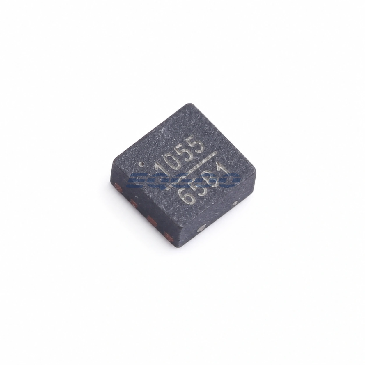
Technical Specifications
| Parameter | Confirmed Information |
|---|---|
| Technology | GaAs RF switch |
| Topology | SPST |
| Frequency range | 0.5 GHz to 4.0 GHz |
| Insertion loss | 0.7 dB typical at 2.0 GHz |
| Input IP3 | >60 dBm typical |
| Control voltage | 0 V or 3 V |
| RF1 off-state | Reflective open |
| RF2 off-state | 50 Ω terminated |
| Package | 8-lead LFCSP, 2 × 2 mm with exposed pad |
| Exact model lifecycle | Production |
| Family design guidance | Recommended for new designs |
Design Considerations
The asymmetric off-state termination should be reflected in the signal-chain orientation. If a matched termination is needed on the disabled side, connect the system so the RF2 behavior serves that requirement rather than assuming either RF pin can be interchanged without consequence.
The very high IP3 headline does not remove the need to check compression and loss at the intended frequency and input power. Use the exact frequency-dependent curves for the application band and preserve the exposed-pad grounding recommended for the LFCSP.
Related Engineering Resources
Quality & Verification Support
Third-party inspection or testing can be arranged according to customer requirements. Testing fees are borne by the buyer. Additional verification requirements can be discussed before shipment. After an order is placed, physical product, label, packaging, and Date Code photos may be provided where appropriate.
Request a Quote
To request a quotation, provide the manufacturer part number, required quantity, destination, target Date Code if applicable, and any testing or inspection requirements.