
Key Selection Information
| Selection Parameter | Confirmed Information |
|---|---|
| Battery Configuration | 1-cell Li-Ion, 4.20 V regulation |
| Charger Architecture | Linear charger with dynamic power-path management (DPPM) |
| Fast-Charge Current | 100 mA to 1.5 A, programmed with RISET |
| Regulated System Output | 5.5 V typical with valid input power |
| Input Operating Range | 4.35 V to 6.4 V recommended |
| Input OVP | 6.6 V typical |
| Exact Variant Function | SYSOFF disconnects the battery from the system output |
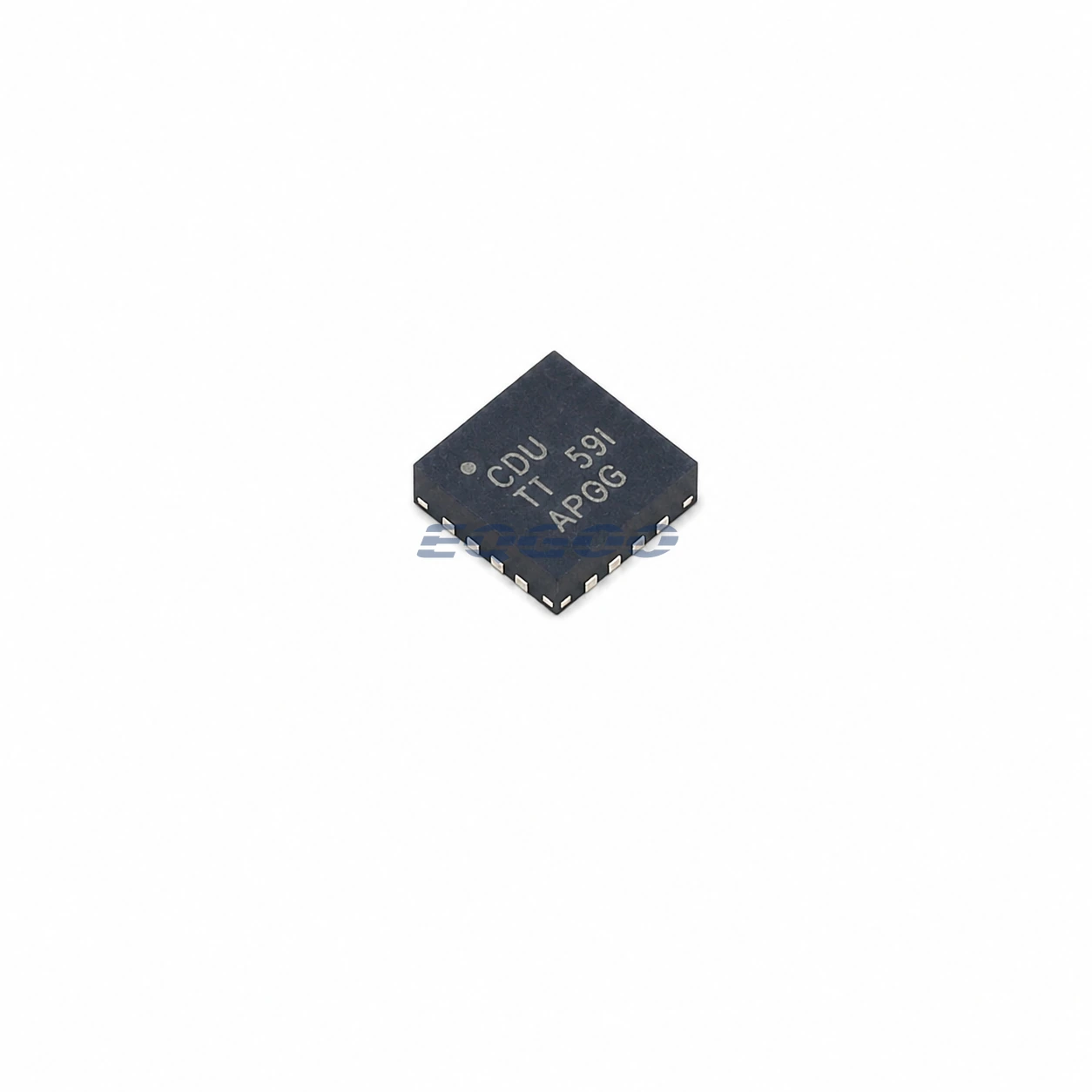
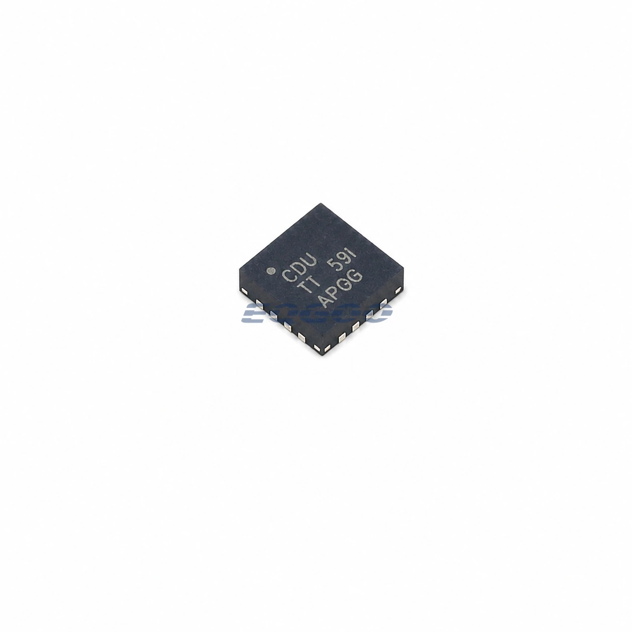
| Exact Package / Packing | VQFN (RGT), 16 pins, 3 mm × 3 mm; 3000-piece large tape and reel |
Product Overview
BQ24075RGTR is a Texas Instruments single-cell linear charger with dynamic power-path management and a 5.5 V regulated system-output target. It charges a 4.2 V Li-Ion cell while independently powering OUT, reducing battery charge current when the input-current budget is needed by the system and allowing the battery to supplement OUT when source power is insufficient.
The 5.5 V OUT regulation is an exact BQ24075 family choice. It differs from BQ24073 and BQ24074, which regulate OUT around 4.4 V. The higher system-output target can be useful when downstream circuitry is designed around a nominal 5 V rail, but the available OUT voltage still depends on input headroom, current demand, DPPM operation, and whether the battery is supplementing the system.
BQ24075 also adds SYSOFF. Driving SYSOFF high turns off the battery-to-system FET so the battery is disconnected from OUT. TI identifies uses such as system load isolation, factory operation without allowing battery discharge into the system, and battery open-circuit-voltage measurements required by some fuel-gauging methods.
For related power-path charger options, see HKEQGOO’s Battery Chargers category.
Technical Specifications
| Parameter | Verified Information |
|---|---|
| Manufacturer | Texas Instruments |
| Exact MPN | BQ24075RGTR |
| Battery Charge Voltage | 4.20 V typical; 4.16 V minimum, 4.23 V maximum |
| System Output Regulation | 5.5 V typical; 5.4 V minimum, 5.6 V maximum |
| Recommended Input Operating Range | 4.35 V to 6.4 V |
| Input OVP Threshold | 6.6 V typical; 6.4 V minimum, 6.8 V maximum |
| Fast-Charge Current Range | 100 mA to 1.5 A |
| Fast-Charge Factor | 890 AΩ typical |
| Programmable Input Limit | 200 mA to 1.5 A using RILIM, plus fixed 100 mA / 500 mA modes |
| DPPM Threshold | 4.3 V typical for BQ24075 |
| Battery Supplement Entry | OUT at or below approximately VBAT − 40 mV under the stated condition |
| Internal Termination Threshold | 10% of fast-charge current typical outside USB100 mode; 3.3% typical in USB100 mode |
| Thermal Regulation | 125°C |
| Thermal Shutdown | 155°C rising, 20°C hysteresis |
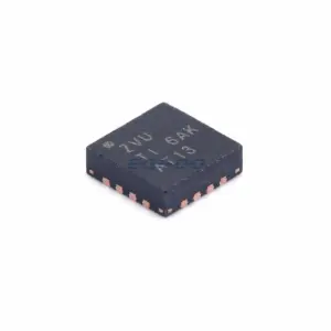
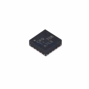
| Package | VQFN (RGT), 16 pins, 3 mm × 3 mm |
| Manufacturer Status | Active / Production |
| Part Marking | CDU |
Functional Highlights
The 5.5 V OUT target separates system-rail selection from battery voltage
BQ24075 regulates the battery to 4.2 V but targets 5.5 V at OUT when the input source has sufficient voltage and current. The system rail is therefore not simply the battery voltage plus a small offset. This distinguishes BQ24075 from the 4.4 V OUT variants in the same family.
The regulated target still depends on headroom. If the input source is too low or source current is insufficient, DPPM and battery-supplement behavior take over. A designer should not treat 5.5 V as a guaranteed system voltage under every input, load, or battery condition.
SYSOFF provides a deliberate battery-to-system disconnect
The SYSOFF input controls the internal FET between BAT and OUT. With SYSOFF high, that path is turned off so the battery does not support the system output. With SYSOFF low, normal power-path and battery-supplement operation are available.
This is materially different from charger-disable control. CE can stop battery charging while OUT remains active, whereas SYSOFF specifically affects the battery-to-system connection. The required shipping, factory-test, fuel-gauge, and system-off behavior should determine how both controls are wired.
DPPM still prioritizes the system load before charging
BQ24075 reduces charge current when the system output approaches its 4.3 V DPPM threshold. If reducing charge current to zero cannot support the load, the battery can enter supplement mode unless SYSOFF has disconnected it.
This means the programmed 1.5 A battery current, programmable input-current limit, system load, and SYSOFF state all interact. Battery charging is the flexible part of the power budget when the system needs more input power.
Design Considerations
- Verify that the 5.5 V OUT target matches downstream circuitry. It is intentionally higher than the 4.4 V output of BQ24073/BQ24074 and should not be treated as a drop-in electrical equivalent.
- Separate CE and SYSOFF functions in the power-state design. CE disables charging; SYSOFF disconnects the battery from OUT. They solve different system-control requirements.
- Size the input source for both system and charge demand. DPPM reduces battery current as the system consumes more of the input-current budget.
- Use the BQ24075 input range, not the 28 V absolute rating, for normal operation. Recommended operation is 4.35 V to 6.4 V with 6.6 V typical OVP.
- Provide adequate exposed-pad thermal layout. At high charge current, linear dissipation can activate 125°C thermal regulation and reduce battery current below its programmed value.
Product Status and Exact Order Code
Manufacturer status: Active / Production
Texas Instruments lists BQ24075RGTR as a 16-pin VQFN RGT device supplied in a 3000-piece large tape-and-reel carrier with Level-2-260C-1 YEAR MSL classification, an operating-temperature listing of −40°C to +85°C, and part marking CDU. BQ24075RGTT is the corresponding 250-piece small tape-and-reel option.
Related Engineering Resources
Quality & Verification Support
Third-party inspection or testing can be arranged according to customer requirements. Testing fees are borne by the buyer. Additional verification requirements can be discussed before shipment. After an order is placed, physical product, label, packaging, and Date Code photos may be provided where appropriate.
Request a Quote
To request a quotation, provide the manufacturer part number, required quantity, destination, target Date Code if applicable, and any testing or inspection requirements.