Key Selection Information
| Selection Parameter | Confirmed Information |
|---|---|
| Package | TSSOP-20 |
| Supply voltage | 2.4V~3.6V |
| CPU Core | ARM Cortex-M0 |
| Maximum CPU speed | 48MHz |
| Program memory | 16KB |
| Operating Temperature | -40℃~+85℃ |
| Number of I/O | 15 |
Compact 16 KB STM32F0 configuration
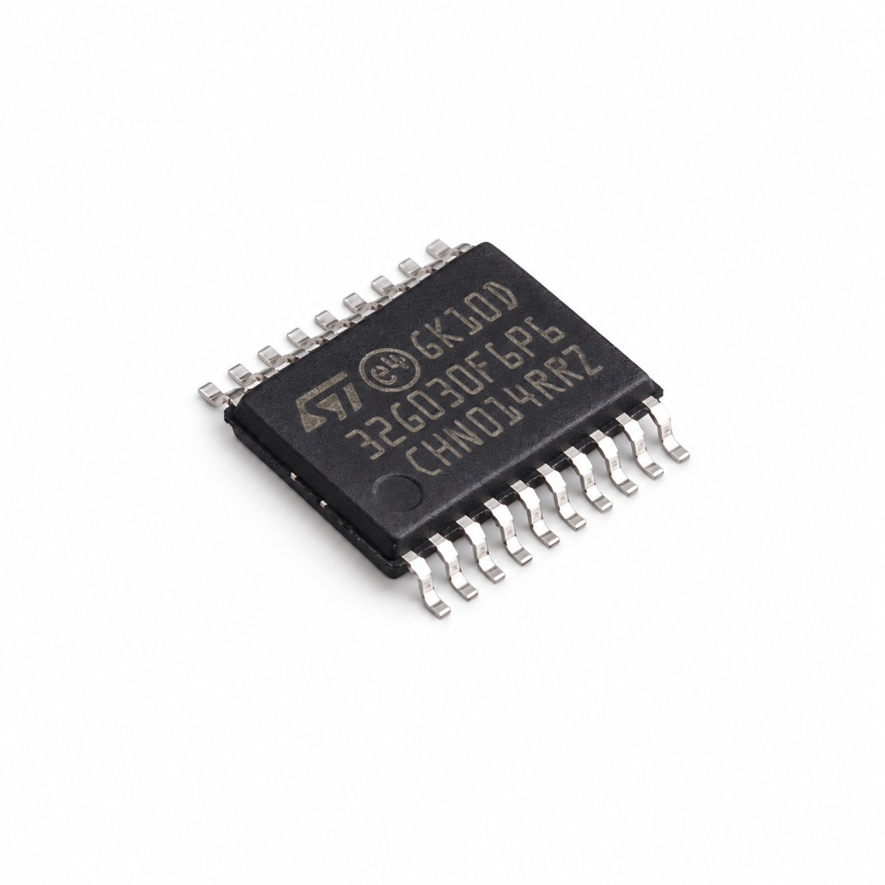
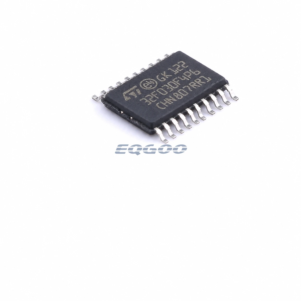
STM32F030F4P6TR is the 16 KB Flash version of ST’s STM32F030 value-line Cortex-M0 family in a TSSOP-20 package. It runs at up to 48 MHz from a 2.4 V to 3.6 V supply and ST lists the exact orderable as active and industrial grade.
The package is intentionally small: ST’s exact-orderable table lists 15 I/Os, one SPI, one USART and nine ADC channels for this configuration. That makes the F4P6TR a very different design choice from larger STM32F030C8 or K6 parts even though they share the same 48 MHz Cortex-M0 family.
Technical Specifications
| Parameter | Value |
|---|---|
| Package | TSSOP-20 |
| Supply voltage | 2.4V~3.6V |
| CPU Core | ARM Cortex-M0 |
| Maximum CPU speed | 48MHz |
| Program memory | 16KB |
| Operating Temperature | -40℃~+85℃ |
| Number of I/O | 15 |
| ADC (Bit) | 12bit |
| Program Memory Type | FLASH |
| Core Size | 32 Bit |
| Oscillator Type | Built-in |
What limits the F4P6TR in practice
The main selection boundary is the combination of 16 KB Flash and a 20-pin package. It works best when firmware and pin requirements are known early and remain compact. A design that later needs a second serial interface, substantially more code space or more GPIO should move to a larger STM32F030 orderable rather than trying to solve those limits in software.
Pin and memory budget
ST lists 15 I/Os and nine ADC channels for the exact F4P6TR configuration. With only one SPI and one USART, interface allocation should be decided before the PCB is frozen. The 16 KB Flash ceiling also makes bootloader size, libraries and future feature growth important at the start of the project rather than after firmware integration.
Best-fit use
This part suits compact embedded-control and user-interface functions where a 48 MHz Cortex-M0, basic analog acquisition and a small serial-interface set are sufficient. It is not a USB or CAN MCU; those interfaces should not be assumed from other STM32 families.
TSSOP-20 implementation notes
Check every required signal against the exact TSSOP-20 pinout because the small package, not the family maximum, is the real I/O constraint. Keep the 2.4 V to 3.6 V operating supply in the power-tree budget, and leave Flash margin for production firmware rather than sizing only to the first build.
Related Engineering Resources
- STM32F030F4P6TR Datasheet (PDF) — HKEQGOO-hosted copy of the STMicroelectronics datasheet used for technical review.
- STMicroelectronics product page — official manufacturer product, lifecycle, ordering and documentation resource.
Quality & Verification Support
Third-party inspection or testing can be arranged according to customer requirements. Testing fees are borne by the buyer. Additional verification requirements can be discussed before shipment. After an order is placed, physical product, label, packaging, and Date Code photos may be provided where appropriate.
Request a Quote
To request a quotation, provide the manufacturer part number, required quantity, destination, target Date Code if applicable, and any testing or inspection requirements.
For a 32-KB Flash version in the STM32F030 family rather than this 16-KB TSSOP-20 option, compare STM32F030K6T6 in LQFP-32. The package and number of available I/O connections differ, so the PCB layout, peripheral pin mapping and firmware memory budget must be checked before selecting a different ordering code.