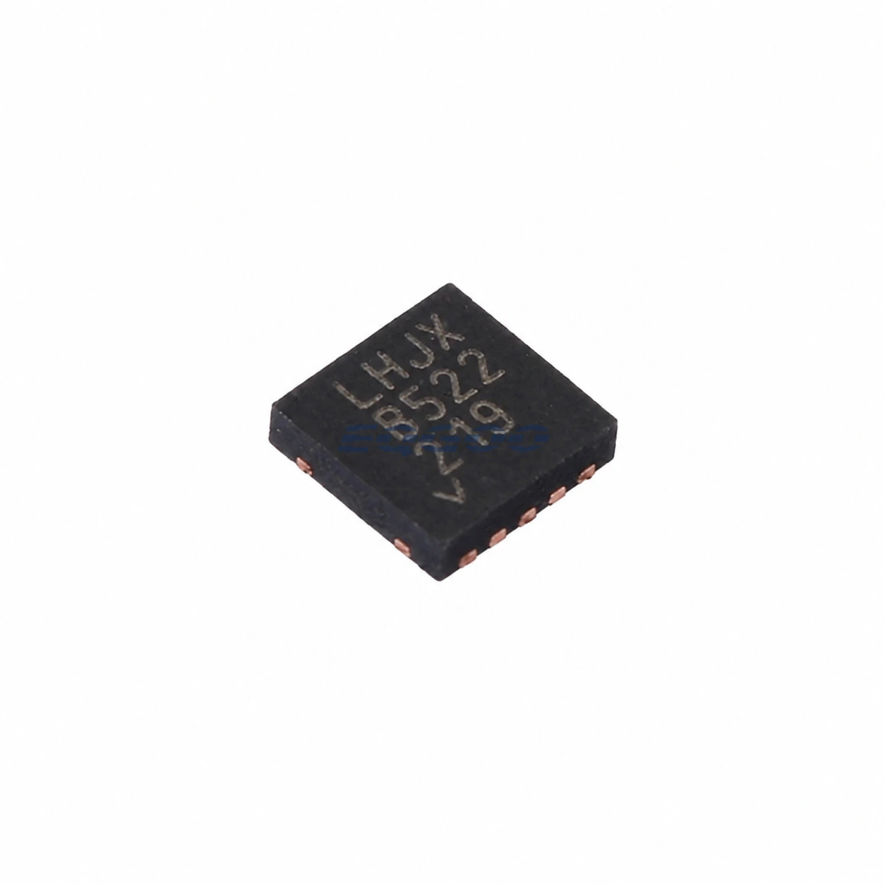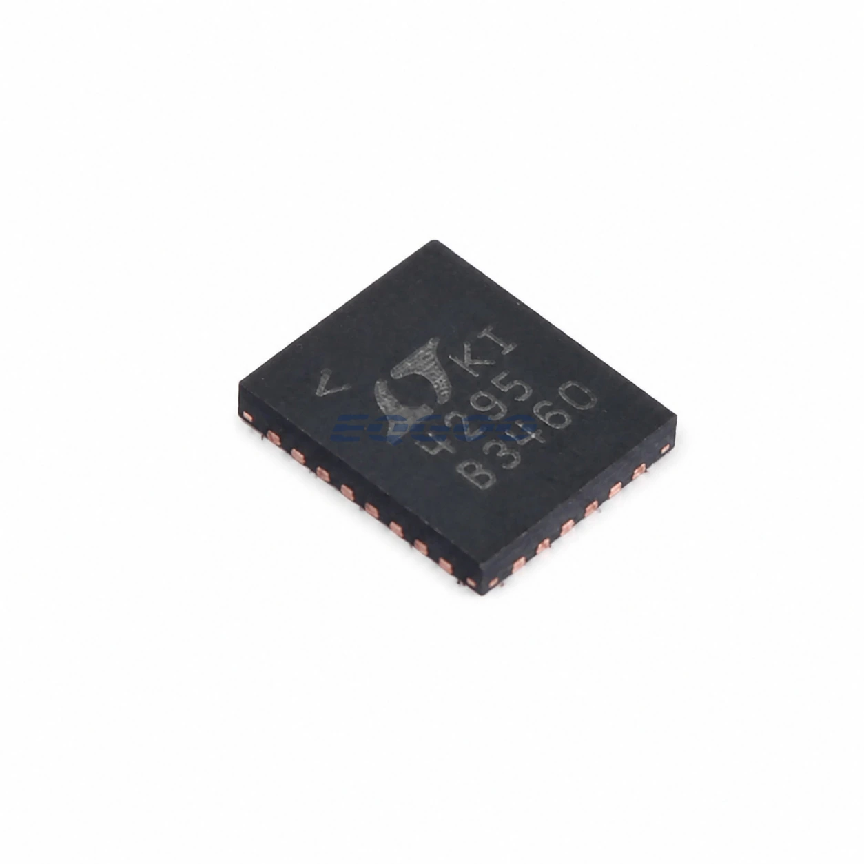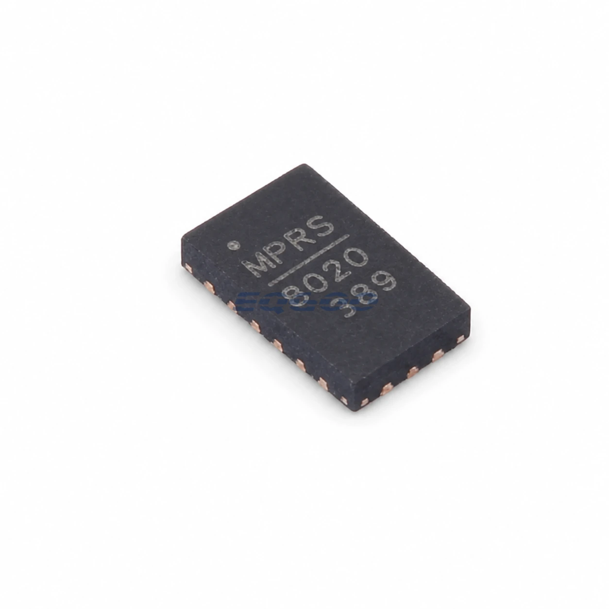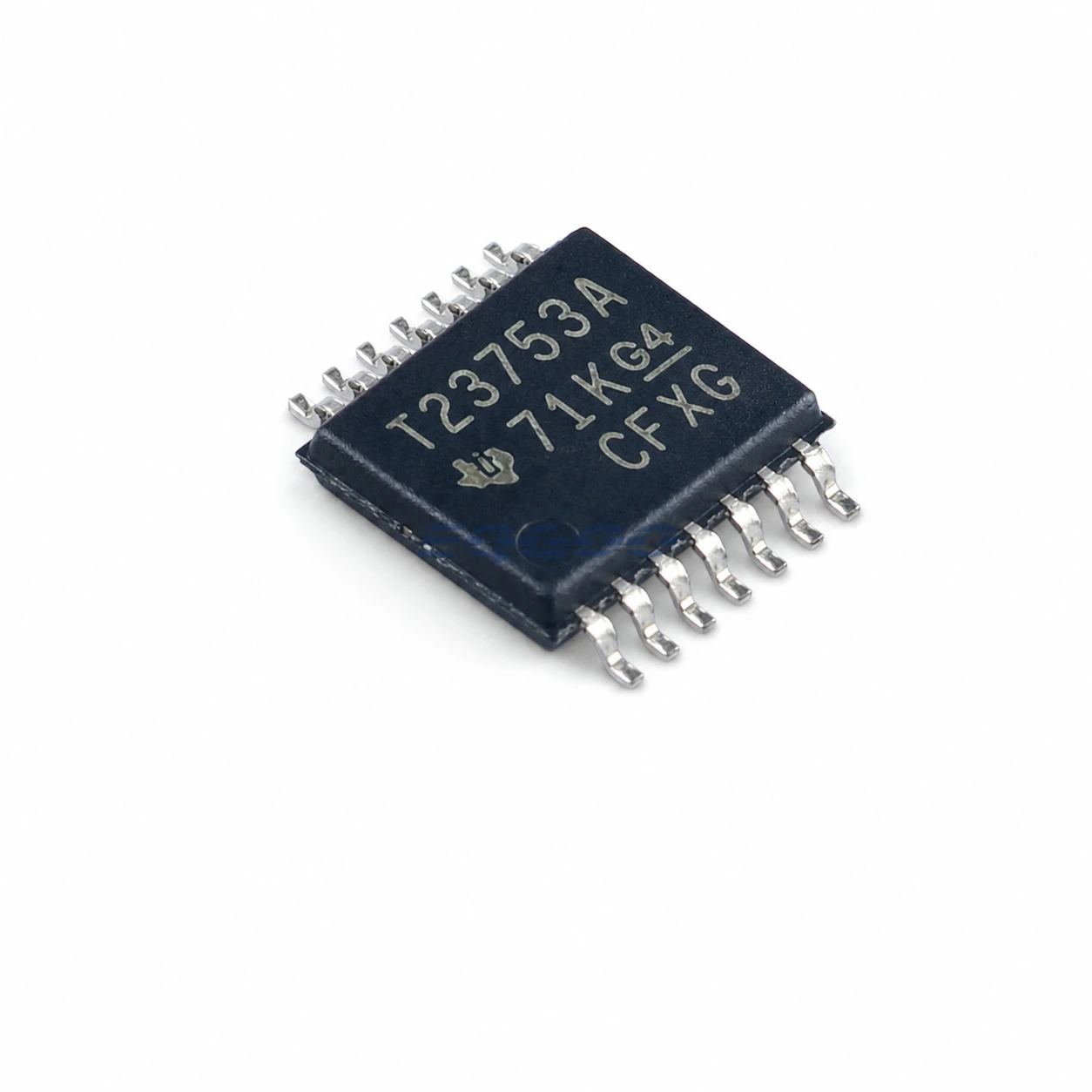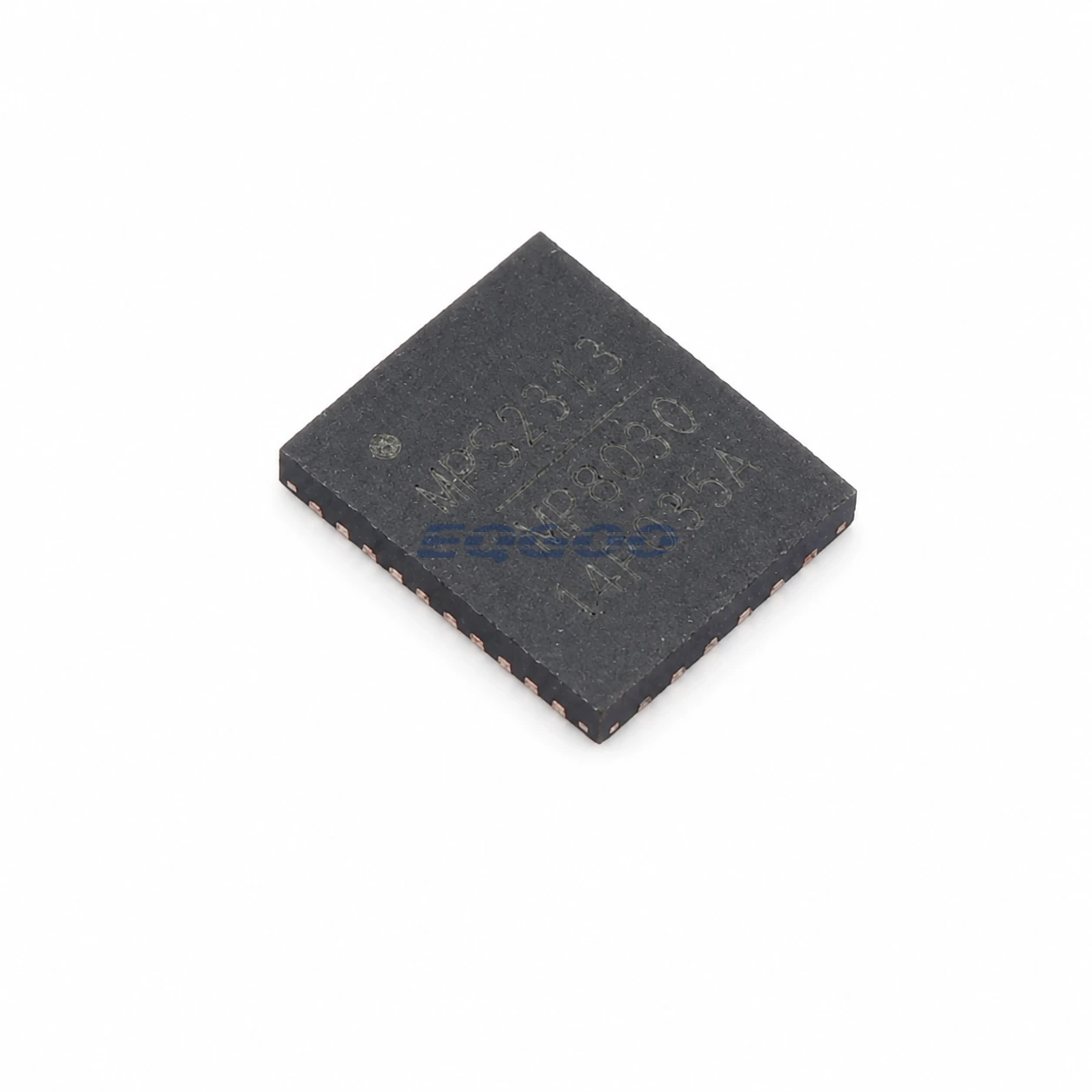
Key Selection Information
| Selection Parameter | Confirmed Information |
|---|---|
| Function | Fully integrated IEEE 802.3af/at/bt PoE PD interface with flyback/forward controller |
| Maximum PD output class | Up to 71.3 W / Class 8 design support |
| Internal hot-swap MOSFET | Used for designs up to 51 W |
| Higher-power path | External FET driven by GATE1 above 51 W |
| Converter modes | PSR flyback, SSR flyback, SSR active-clamp forward |
| Gate drive | 2 A source capability stated by MPS |
| Soft start | 15 ms |
| Packing suffix | -Z tape-and-reel |
Product Overview
The MP8030GQJ-Z is the tape-and-reel ordering option of MPS’s MP8030 high-power PoE powered-device solution. It integrates the IEEE 802.3af/at/bt PD interface with a high-efficiency flyback/forward controller and supports designs extending to the 71.3 W Class 8 PD power level.
The device uses an internal hot-swap MOSFET for designs up to 51 W and supports an external MOSFET through GATE1 for higher-power applications. Its DC/DC controller can operate primary-side-regulated flyback, secondary-side-regulated flyback or secondary-side-regulated active-clamp forward topologies.
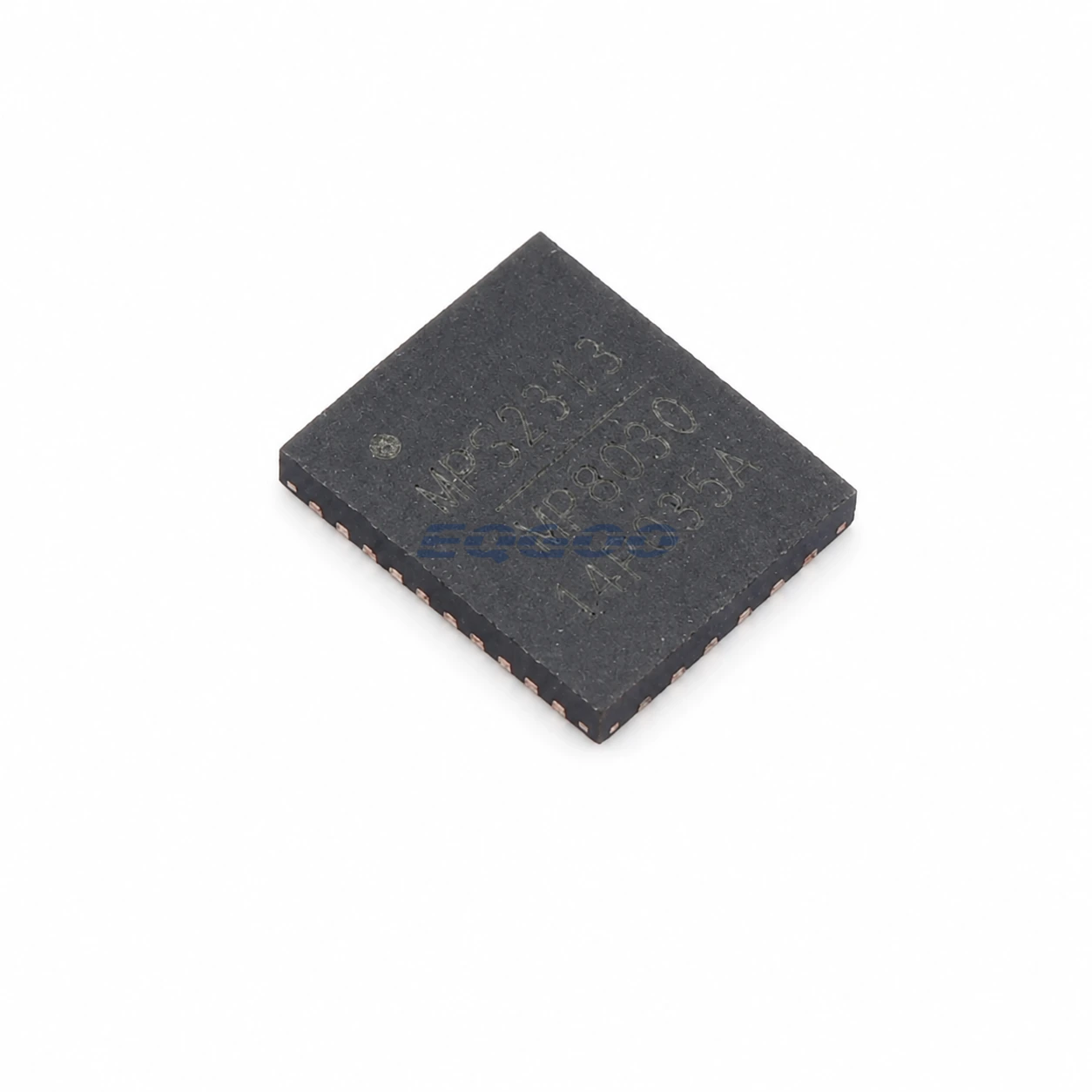
Technical Specifications
| Parameter | Confirmed Information |
|---|---|
| PoE compliance | IEEE 802.3af / 802.3at / 802.3bt |
| Maximum supported PD power | 71.3 W class design |
| Internal hot-swap MOSFET | 100 V class, 0.35 Ω noted in MPS selector material |
| Internal MOSFET application | ≤51 W designs |
| External high-power FET | GATE1 for >51 W designs |
| Auxiliary-adapter FET drive | GATE2 N-channel MOSFET driver |
| Supported topologies | PSR flyback, SSR flyback, SSR active-clamp forward |
| Main gate drive capability | 2 A class |
| Synchronous drive | 0.8 A class |
| Soft-start time | 15 ms |
| EMI feature | Frequency dithering |
| Package | QFN-32, 5 mm × 6 mm |
| Reel quantity | 5,000 for -Z order code |
Design Considerations
The 71.3 W figure is a system-level PoE class capability, not a guaranteed load output under arbitrary conditions. Above 51 W, MPS explicitly moves to an external power FET path; transformer, converter topology, thermal design and cable/class allocation must all support the intended load.
MPS provides both PSR and SSR architectures. PSR can simplify secondary feedback, while SSR/active-clamp forward can improve regulation or efficiency at higher power. Select the feedback mode before finalizing transformer construction and compensation.
Related Engineering Resources
Quality & Verification Support
Third-party inspection or testing can be arranged according to customer requirements. Testing fees are borne by the buyer. Additional verification requirements can be discussed before shipment. After an order is placed, physical product, label, packaging, and Date Code photos may be provided where appropriate.
Request a Quote
To request a quotation, provide the manufacturer part number, required quantity, destination, target Date Code if applicable, and any testing or inspection requirements.