Key Selection Information
| Selection Parameter | Confirmed Information |
|---|---|
| Function | RF/IF gain/loss and phase detector |
| Input frequency | Low frequency to 2.7 GHz |
| Input level range | -60 dBm to 0 dBm in 50 Ω |
| Gain/loss measurement | ±30 dB, 30 mV/dB |
| Phase measurement | 0° to 180°, 10 mV/degree |
| Envelope bandwidth | DC to 30 MHz |
| Supply voltage | 2.7 V to 5.5 V |
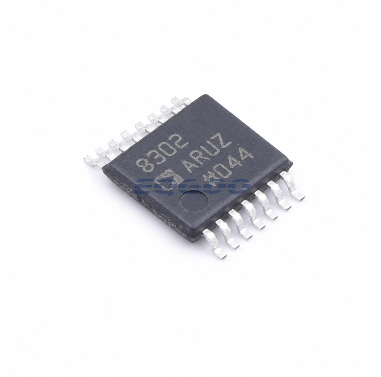
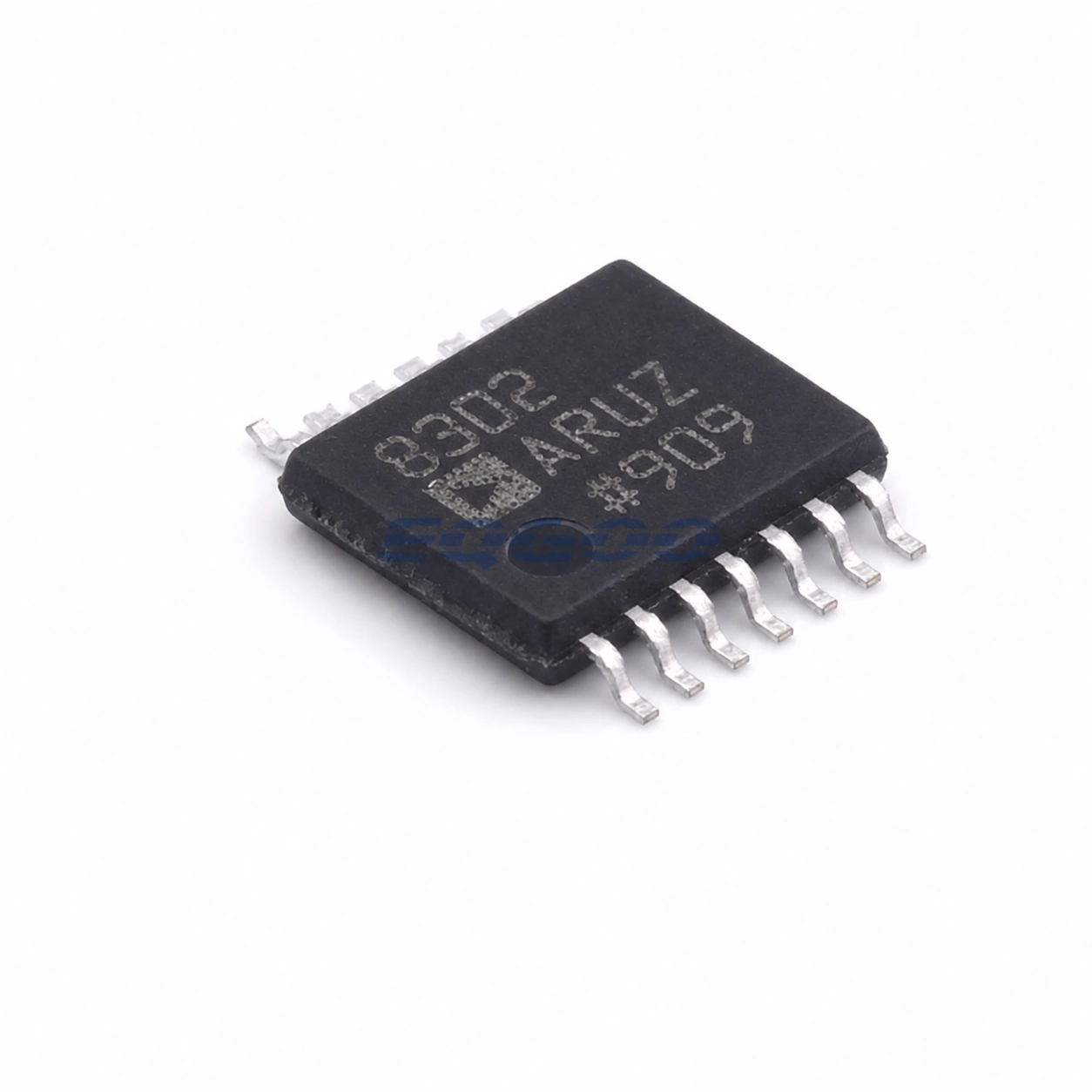
| Package | 14-lead TSSOP |
Product Overview
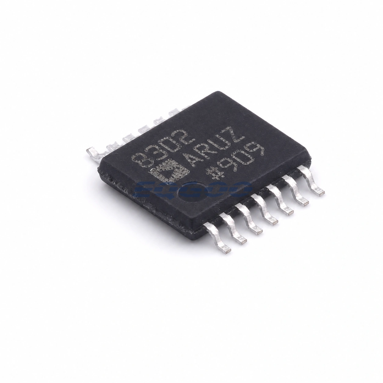
The AD8302ARUZ-RL7 is the 7-inch reel order form of Analog Devices’ AD8302 integrated gain/loss and phase detector. It compares two RF or IF inputs from low frequency to 2.7 GHz and produces separate analog outputs proportional to relative magnitude and phase, allowing a single IC to monitor two dimensions of a signal path.
The magnitude channel covers ±30 dB with 30 mV/dB scaling, while the phase channel covers 0° to 180° with 10 mV/degree scaling. Analog Devices specifies typical magnitude nonlinearity below 0.5 dB and typical phase nonlinearity below 1°. The exact RL7 suffix changes the reel packing rather than the electrical function, so board-level behavior is the same AD8302 TSSOP device family.
Technical Specifications
| Parameter | Confirmed Information |
|---|---|
| Measurement type | Relative gain/loss and phase |
| Frequency range | LF to 2.7 GHz |
| Input range | -60 dBm to 0 dBm in a 50 Ω system |
| Magnitude range | ±30 dB |
| Magnitude slope | 30 mV/dB |
| Typical magnitude nonlinearity | <0.5 dB |
| Phase range | 0° to 180° |
| Phase slope | 10 mV/degree |
| Typical phase nonlinearity | <1° |
| Envelope bandwidth | DC to 30 MHz |
| Supply voltage | 2.7 V to 5.5 V |
| Reference output | 1.8 V |
| Package | 14-lead TSSOP |
| Product status | Production |
Design Considerations
The two detector channels compare signal paths, so external amplitude balance, phase delay and impedance matching affect the measured result. For precision measurement, route the two inputs symmetrically and account for fixture or PCB phase offset during calibration.
The DC-to-30 MHz envelope bandwidth describes how quickly the detector outputs can follow changes in the RF/IF signals; it is not the RF carrier bandwidth. This distinction is important when using the part for closed-loop gain/phase control or modulation-envelope measurements.
Related Engineering Resources
Quality & Verification Support
Third-party inspection or testing can be arranged according to customer requirements. Testing fees are borne by the buyer. Additional verification requirements can be discussed before shipment. After an order is placed, physical product, label, packaging, and Date Code photos may be provided where appropriate.
Request a Quote
To request a quotation, provide the manufacturer part number, required quantity, destination, target Date Code if applicable, and any testing or inspection requirements.