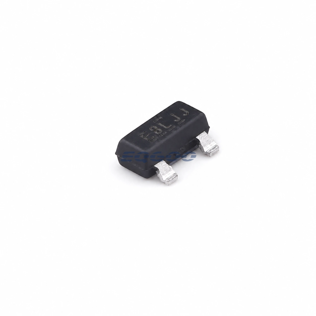
Key Selection Information
| Selection Parameter | Confirmed Information |
|---|---|
| Manufacturer | Infineon Technologies |
| Exact MPN | IRLML6402TRPBF |
| Product Category | MOSFETs |
| Package | SOT-23 |
| Packing | 3,000 pcs/reel |
| Configuration | 1 P-channel |
| Drain-Source Voltage (VDSS) | 20V |
| Continuous Drain Current (ID) | 3.7A |
| On-Resistance (RDS(on)) | 65mΩ@4.5V |
Product Overview
-20 V single P-channel HEXFET® power MOSFET; exact MPN verified.
The device is suitable for compact low-voltage load switching, but its negative gate rating and SOT-23 thermal limit must be respected. At only -2.5 V gate drive, the maximum resistance rises to 135 mΩ.
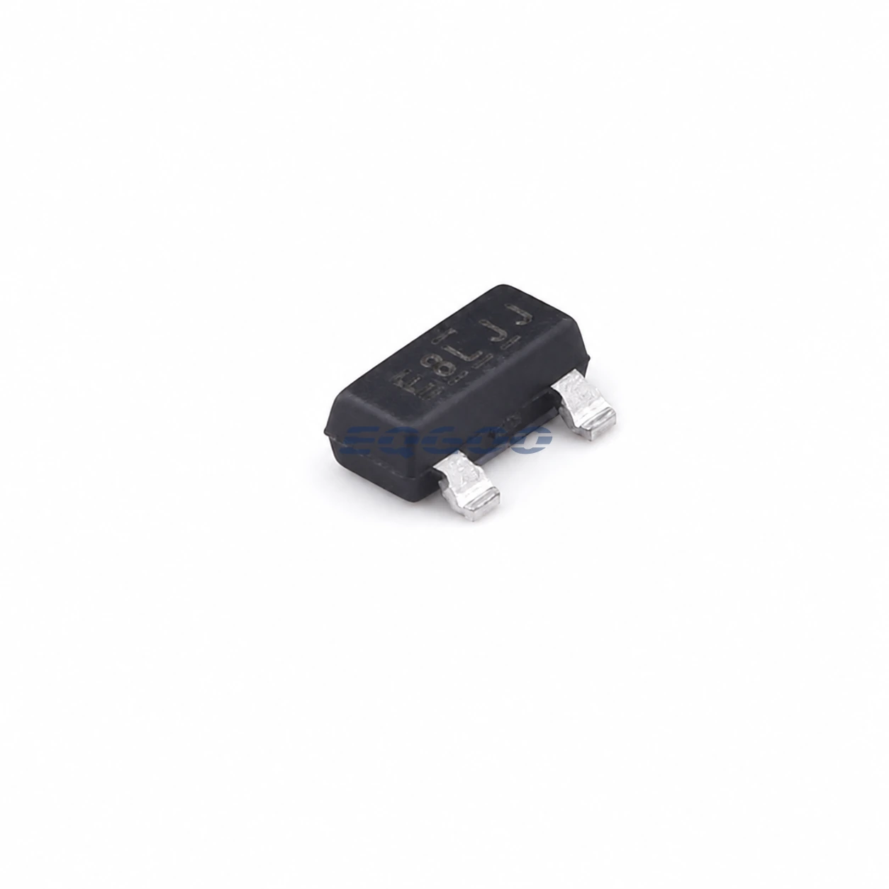
Technical Specifications
| Parameter | Verified Information |
|---|---|
| Manufacturer | Infineon Technologies |
| Exact MPN | IRLML6402TRPBF |
| Functional Category | MOSFETs |
| Package | SOT-23 |
| Packing | 3,000 pcs/reel |
| Source Catalog ID | C2593 |
| Configuration | 1 P-channel |
| Drain-Source Voltage (VDSS) | 20V |
| Continuous Drain Current (ID) | 3.7A |
| On-Resistance (RDS(on)) | 65mΩ@4.5V |
| Manufacturer Status | Discontinued / end of life. |
Selection Notes
P-channel high-side topology; 20 V rating; gate-drive voltage; SOT-23 thermal dissipation; low-voltage R_{DS(on)}.
Check VDSS margin, continuous/pulsed current, RDS(on) at the actual gate drive and package thermal impedance together.
Manufacturer Decision-Relevant Notes
V_{DS}: -20 V. ; R_{DS(on)}: typ. 50 mΩ, max. 65 mΩ at V_{GS}=-4.5 V, I_D=-3.7 A. ; R_{DS(on)}: typ. 80 mΩ, max. 135 mΩ at V_{GS}=-2.5 V, I_D=-3.1 A. ; Continuous I_D: max. -3.7 A at T_A=25^°C; -2.2 A at T_A=70^°C. ; Pulsed I_D: max. -22 A. ; Gate-source voltage: ±12 V. ; Total gate charge: typ. 8.0 nC, max. 12 nC at I_D=-3.7 A. ; R_{θ JA}: typ. 75 K/W, max. 100 K/W, board-dependent. ; Operating/storage temperature: -55 to +150^°C.
Design Considerations
-
- Verify every gate transient remains within ±12 V. 2. Use the R_{DS(on)} specification corresponding to the actual gate-drive voltage. 3. Calculate board-level thermal rise using the actual copper area and duty cycle. 4. Confirm load transients and inductive energy remain within the -20 V and avalanche limits.
Application Fit
Battery and load management; portable electronics and compact surface-mount designs.
Exact Variant and Procurement Notes
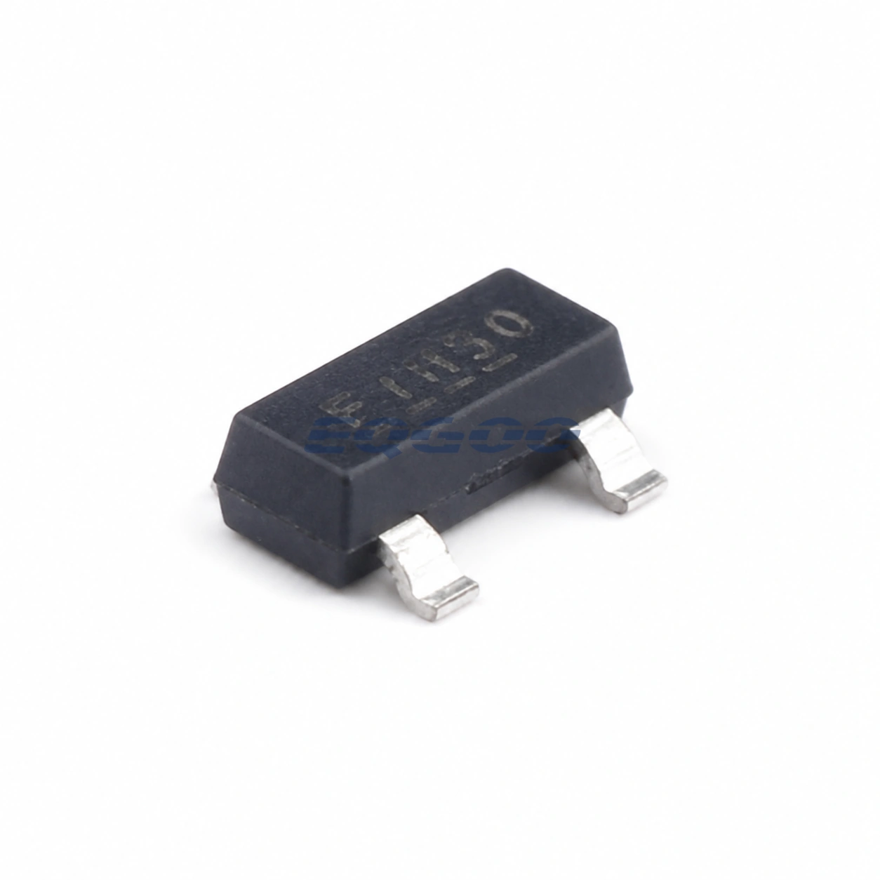
SOT-23 / Micro3™ surface-mount package; exact IRLML6402TRPBF; tape-and-reel, 3,000 units; MSL1. Do not substitute the distinct suffix IRLML6402TRPBF-1.
Manufacturer Resources
Quality & Verification Support
Third-party inspection or testing can be arranged according to customer requirements. Testing fees are borne by the buyer. Additional verification requirements can be discussed before shipment. Physical product, label, packaging, and Date Code photos may be provided where appropriate.
Request a Quote
For IRLML6402TRPBF quotation, provide the exact MPN, required quantity, destination, target Date Code if applicable, and any inspection or testing requirements.