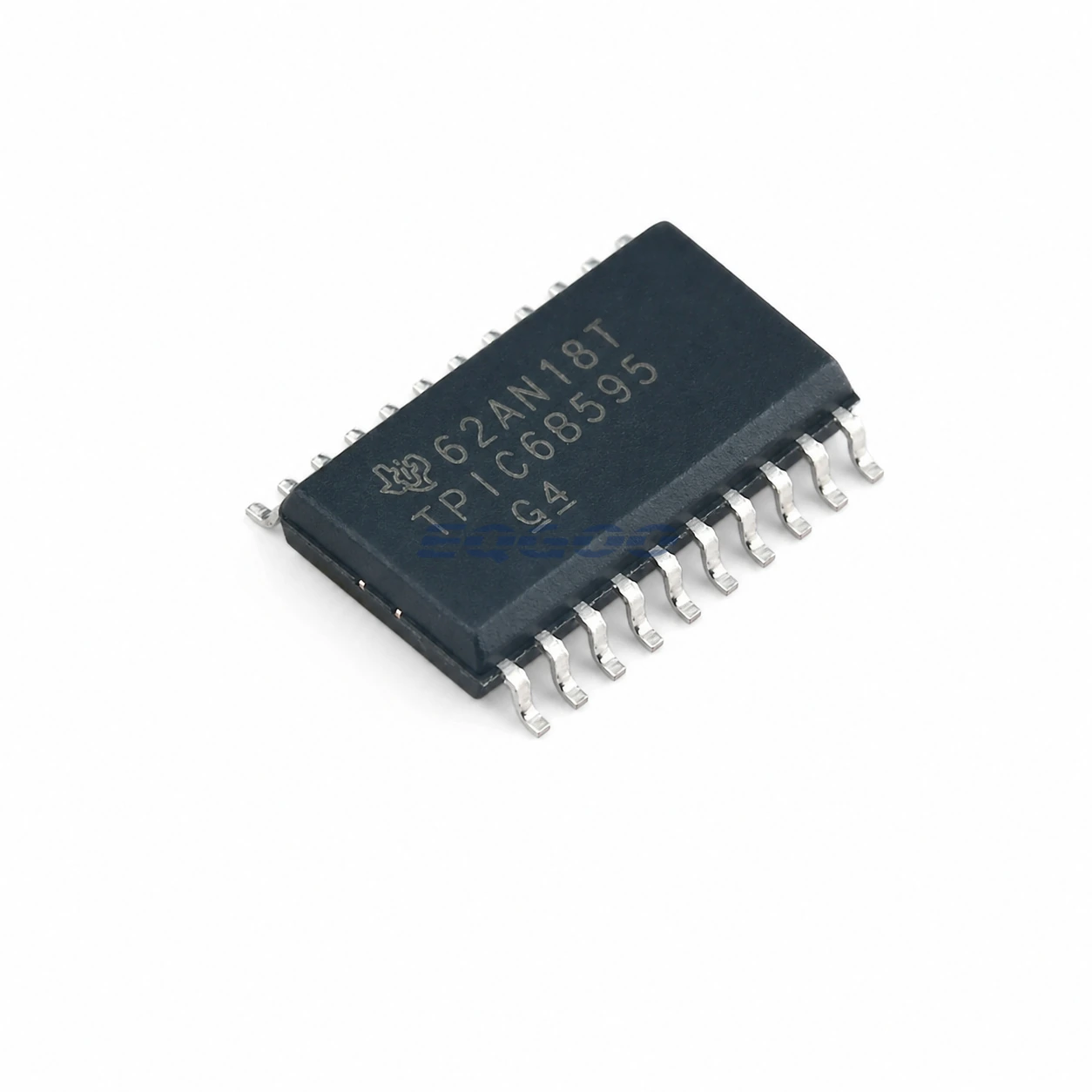

Key Selection Information
| Selection Parameter | Confirmed Information |
|---|---|
| Logic | 8-bit serial-in shift register plus storage register |
| Outputs | 8 open-drain DMOS power outputs |
| Current | 150 mA continuous per output stated feature |
| Clamp | 50 V output clamp for inductive transients |
| RDS(on) | 5 Ω typical stated feature |
| Avalanche | 30 mJ stated avalanche energy |
| Cascade | Serial output supports daisy chaining |
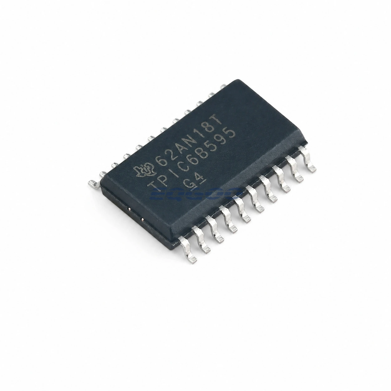
| Exact Package / Packing | SOIC (DW), 20 pins; 2000-piece large tape and reel |
Product Overview
TPIC6B595DWR combines the familiar shift-register-plus-latch architecture with eight high-voltage low-side DMOS outputs, so it can directly sink lamps, relays, solenoids or LED loads that ordinary HC595 logic cannot drive.
The output clamp is especially relevant for inductive loads: the driver can absorb controlled flyback energy without a separate clamp at every channel, provided the load energy stays inside the device avalanche/thermal limits.
The outputs are open-drain low-side switches rather than logic-level push-pull pins. Load supply voltage, current, duty cycle and package dissipation therefore belong in the design calculation.
For related devices, see HKEQGOO’s Shift Registers category.
Technical Specifications
| Parameter | Verified Information |
|---|---|
| Manufacturer | Texas Instruments |
| Exact MPN | TPIC6B595DWR |
| Logic | 8-bit serial-in shift register plus storage register |
| Outputs | 8 open-drain DMOS power outputs |
| Current | 150 mA continuous per output stated feature |
| Clamp | 50 V output clamp for inductive transients |
| RDS(on) | 5 Ω typical stated feature |
| Avalanche | 30 mJ stated avalanche energy |
| Cascade | Serial output supports daisy chaining |
| Exact Package / Packing | SOIC (DW), 20 pins; 2000-piece large tape and reel |
| Manufacturer Status | Active / Production |
| Part Marking | TPIC6B595 |
Functional Highlights
Power output stage removes a separate transistor array
Serial expansion and load switching are integrated in one IC, reducing BOM and routing for multi-channel indicators/relays.
50 V clamp does not make every inductive load automatically safe
Coil current and inductance determine avalanche energy. Repetitive switching also creates package heating, so the 30 mJ feature must be checked against the actual coil and duty cycle.
Design Considerations
- Calculate inductive energy per channel and repetitive thermal load before relying on the internal clamp.
- Keep total package dissipation inside the SOIC thermal limit when several channels conduct simultaneously.
- Remember the outputs only sink current; loads must be connected to the appropriate positive supply.
Product Status and Exact Order Code
Manufacturer status: Active / Production
Texas Instruments lists TPIC6B595DWR as Active / Production; SOIC (DW), 20 pins; 2000-piece large tape and reel; Level-1-260C-UNLIM; −40°C to +125°C; marking TPIC6B595.
Related Engineering Resources
Quality & Verification Support
Third-party inspection or testing can be arranged according to customer requirements. Testing fees are borne by the buyer. Additional verification requirements can be discussed before shipment. After an order is placed, physical product, label, packaging, and Date Code photos may be provided where appropriate.
Request a Quote
To request a quotation, provide the manufacturer part number, required quantity, destination, target Date Code if applicable, and any testing or inspection requirements.