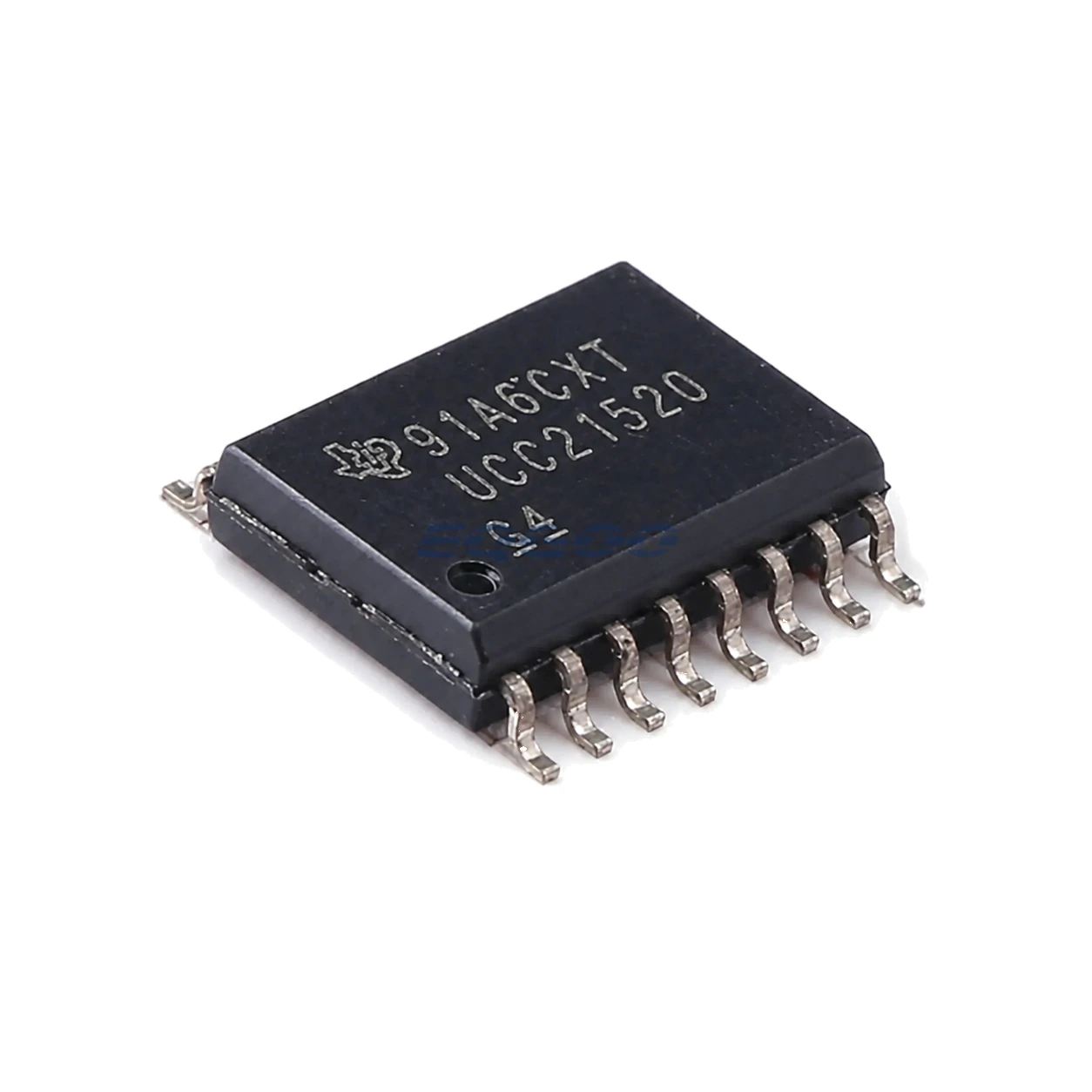

Key Selection Information
| Selection Parameter | Confirmed Information |
|---|---|
| Channels | 2 isolated output channels |
| Drive Strength | 4 A peak source / 6 A peak sink |
| Isolation | 5.7 kVRMS reinforced barrier |
| CMTI | Greater than 125 V/ns stated feature |
| Timing | 33 ns typical propagation delay; programmable overlap/dead time |
| Input / Output Supplies | VCCI 3 V to 18 V; VDD up to 25 V |
| Control | Fast common DISABLE and fail-safe low outputs |
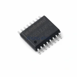
| Exact Package / Packing | SOIC (DW), 16 pins; 2000-piece large tape and reel; marking UCC21520 |
Product Overview
UCC21520DWR is the active large-reel order code for the base UCC21520 dual-channel isolated gate driver. It is suited to half bridges or paired isolated drive channels where one reinforced isolation component replaces two single-channel drivers.
The 4 A source / 6 A sink asymmetry favors strong gate discharge, helping force power switches off quickly during normal commutation or a common DISABLE event. VCCI accepts 3 V to 18 V logic-side supply while each output-side VDD can run up to 25 V.
The exact DWR marking is UCC21520, whereas ADWR is listed as UCC21520A. Their current shared datasheet contains common performance headline values, but exact-order-code control remains important in qualified or lifecycle-managed assemblies.
For related devices, see HKEQGOO’s Isolators – Gate Drivers category.
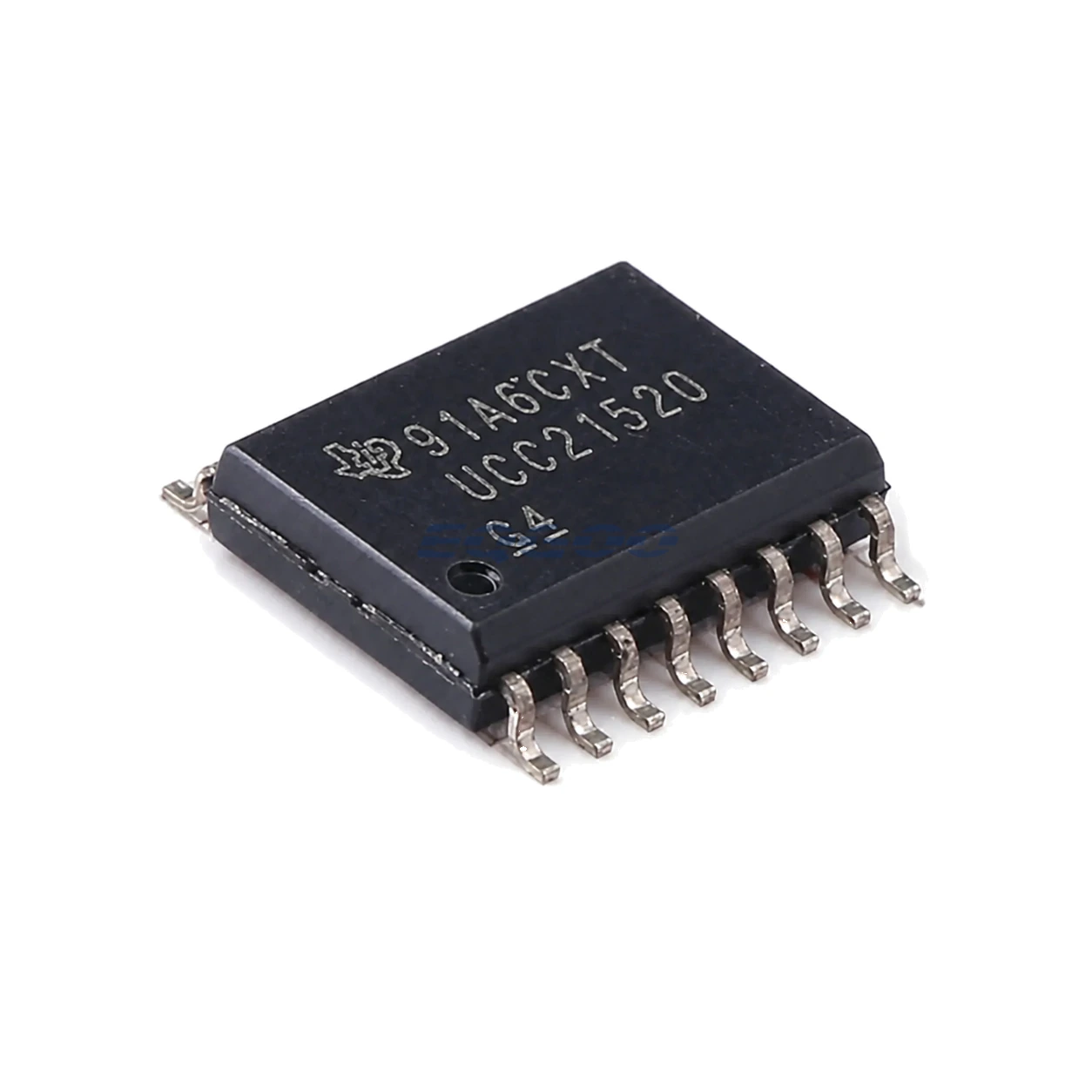
Technical Specifications
| Parameter | Verified Information |
|---|---|
| Manufacturer | Texas Instruments |
| Exact MPN | UCC21520DWR |
| Channels | 2 isolated output channels |
| Drive Strength | 4 A peak source / 6 A peak sink |
| Isolation | 5.7 kVRMS reinforced barrier |
| CMTI | Greater than 125 V/ns stated feature |
| Timing | 33 ns typical propagation delay; programmable overlap/dead time |
| Input / Output Supplies | VCCI 3 V to 18 V; VDD up to 25 V |
| Control | Fast common DISABLE and fail-safe low outputs |
| Exact Package / Packing | SOIC (DW), 16 pins; 2000-piece large tape and reel; marking UCC21520 |
| Manufacturer Status | Active / Production |
| Part Marking | UCC21520 |
Functional Highlights
Two-channel functional isolation supports flexible bridge placement
The secondary channels can be used as high/low half-bridge outputs or as two isolated low/high-side drivers. Their local output supplies and gate loops should be laid out independently.
Fast disable is useful for sequencing but not a substitute for local protection
The common DISABLE response is around the propagation-delay timescale. Short-circuit protection still depends on the system’s sensing, controller and power-switch protection architecture.
Design Considerations
- Keep each secondary gate loop compact and give each output supply local bypassing.
- Program dead time with measured switching behavior and worst-case propagation variation.
- Preserve DWR exact order code where qualification documents or incoming marking control require the base UCC21520 variant.
Product Status and Exact Order Code
Manufacturer status: Active / Production
Texas Instruments lists UCC21520DWR as Active / Production; SOIC (DW), 16 pins; 2000-piece large tape and reel; Level-2-260C-1 YEAR; −40°C to +125°C; marking UCC21520.
Related Engineering Resources
Quality & Verification Support
Third-party inspection or testing can be arranged according to customer requirements. Testing fees are borne by the buyer. Additional verification requirements can be discussed before shipment. After an order is placed, physical product, label, packaging, and Date Code photos may be provided where appropriate.
Request a Quote
To request a quotation, provide the manufacturer part number, required quantity, destination, target Date Code if applicable, and any testing or inspection requirements.