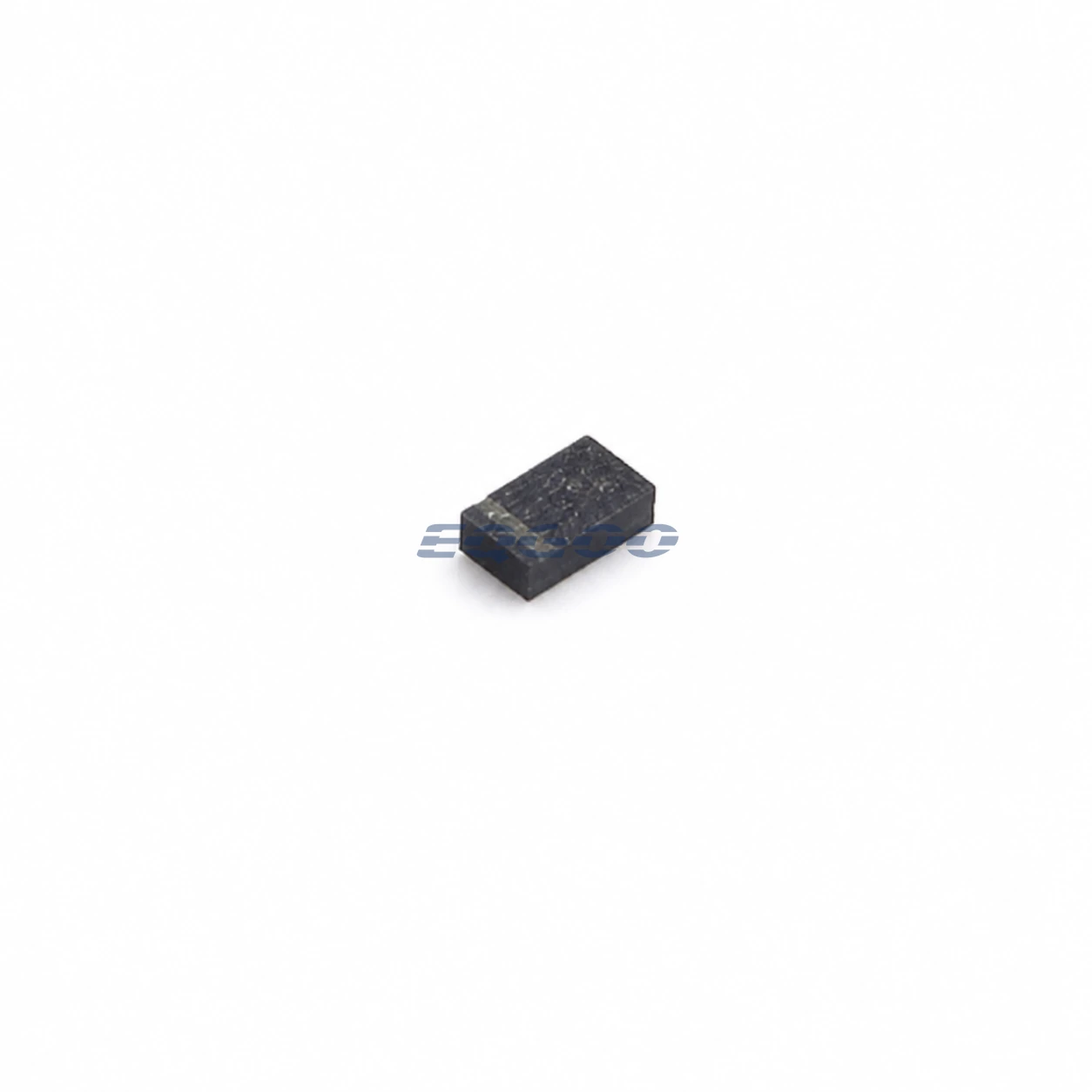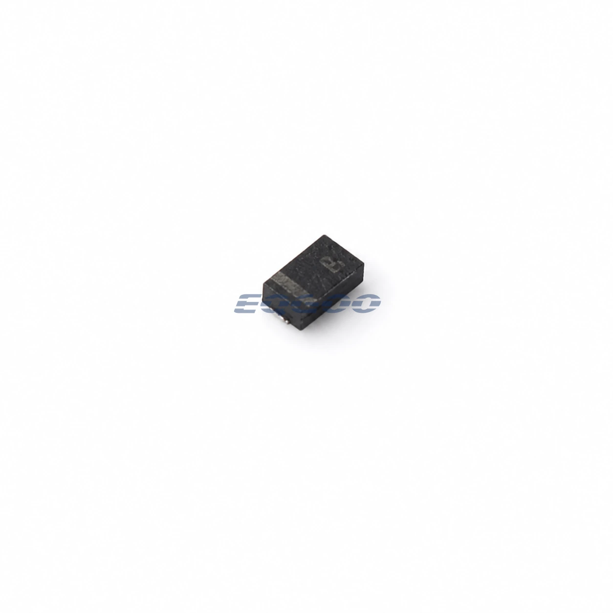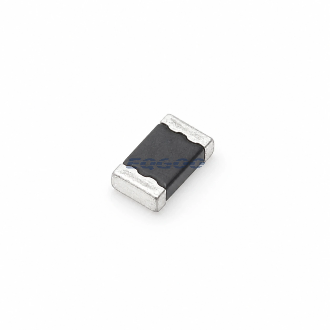
Key Selection Information
| Selection Parameter | Confirmed Information |
|---|---|
| Manufacturer | Littelfuse |
| Exact MPN | PESD0402-140 |
| Product Category | TVS Diodes |
| Package | 0402 |
| Packing | 10,000 pcs/reel |
| Polarity | Bidirectional |
| Reverse Standoff Voltage (VRWM) | 14V |
| Clamping Voltage | 40V |
| Reverse Current (IR) | 10uA |
Product Overview
Bidirectional polymer ESD protector/overvoltage protection device for high-frequency signal interfaces; not a conventional power-bus TVS.
The 0.25 pF typical capacitance and sub-nanosecond response favor high-speed interfaces, while the 40 V TLP clamp is specified under a TLP test—not as a substitute for a 10/1000 µs power-surge rating. ; The manufacturer explicitly cautions against power-bus use; treat this as signal-line ESD protection.
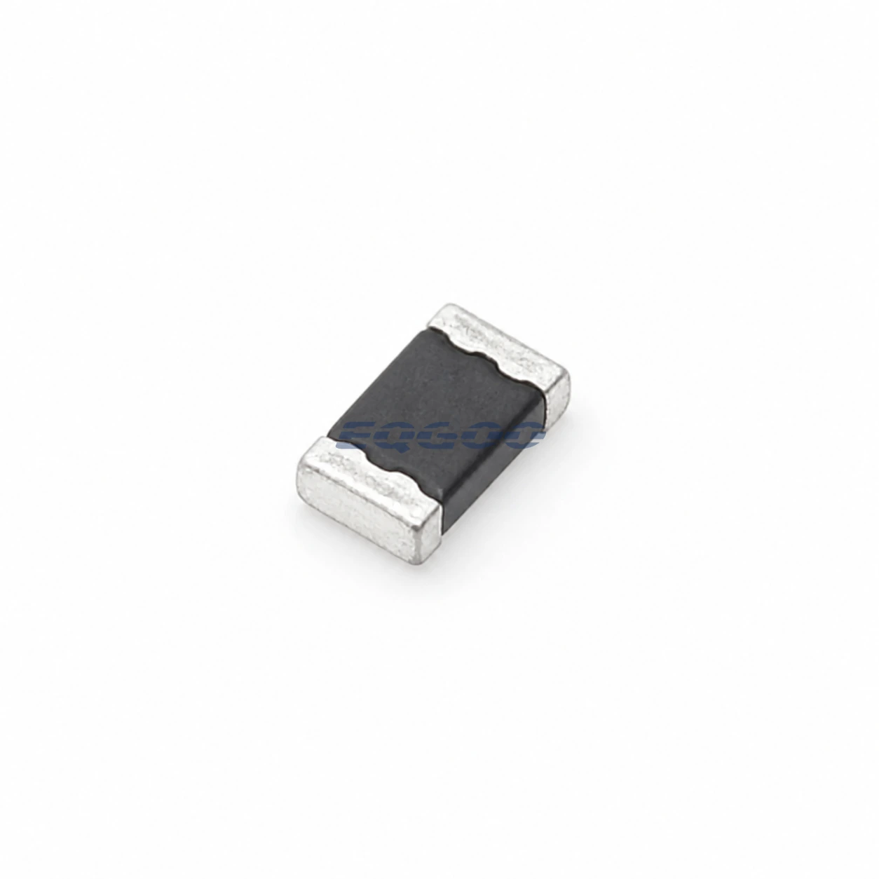
Technical Specifications
| Parameter | Verified Information |
|---|---|
| Manufacturer | Littelfuse |
| Exact MPN | PESD0402-140 |
| Functional Category | TVS Diodes |
| Package | 0402 |
| Packing | 10,000 pcs/reel |
| Source Catalog ID | C10662 |
| Polarity | Bidirectional |
| Reverse Standoff Voltage (VRWM) | 14V |
| Clamping Voltage | 40V |
| Reverse Current (IR) | 10uA |
| Manufacturer Status | Specification status: Released. |
Selection Notes
Ultra-low capacitance; 14 V continuous operating voltage; TLP clamp behavior; 0402 placement density; ESD-only versus surge/power protection.
Coordinate VRWM with the normal signal/rail voltage and verify clamping voltage plus pulse-current/power capability for the surge waveform.
Manufacturer Decision-Relevant Notes
Maximum continuous operating voltage: 14 V DC. ; Typical TLP trigger voltage: 250 V. ; Typical TLP clamping voltage after 30 ns: 40 V. ; Typical capacitance: 0.25 pF at 1 MHz, 1 V RMS. ; Typical leakage: <0.01 µA at 14 V DC; maximum leakage: 10.0 µA at 14 V DC. ; Response time: <1 ns. ; IEC 61000-4-2 contact capability: 8 kV typ, 15 kV max; air: 15 kV typ, 25 kV max. ; ESD pulse withstand: typically 100 pulses under IEC 61000-4-2 level 4 contact testing. ; Operating temperature: -55 to +125 °C; storage: -40 to +85 °C.
Design Considerations
-
- Verify the protected node’s maximum DC operating voltage does not exceed 14 V. 2. Use the 0.25 pF value in insertion-loss, return-loss, and eye-diagram analysis at the actual interface frequency. 3. Confirm the required IEC contact/air discharge level against the separately stated typical and maximum capabilities. 4. Verify the layout, land pattern, and assembly process support the 0402 device and very short ESD current path. 5. Do not apply this part to a power bus without separate manufacturer qualification; the product specification explicitly says not to use it in power-bus applications.
Application Fit
HDMI 1.3, LCD/HDTV, cellular phones, GPS/cell-phone antennas, portable video devices, printer ports, high-speed Ethernet, USB 2.0, IEEE 1394, and DVI.
Exact Variant and Procurement Notes
Exact product PESD0402-140; EIA 0402 form factor; thick-film construction; bidirectional; tape-and-reel packaging is documented as 10,000 pieces, with a 50,000-piece standard-box quantity also listed. The “140” designator denotes 14 V DC operating voltage.
Manufacturer Resources
Quality & Verification Support
Third-party inspection or testing can be arranged according to customer requirements. Testing fees are borne by the buyer. Additional verification requirements can be discussed before shipment. Physical product, label, packaging, and Date Code photos may be provided where appropriate.
Request a Quote
For PESD0402-140 quotation, provide the exact MPN, required quantity, destination, target Date Code if applicable, and any inspection or testing requirements.