Device Overview
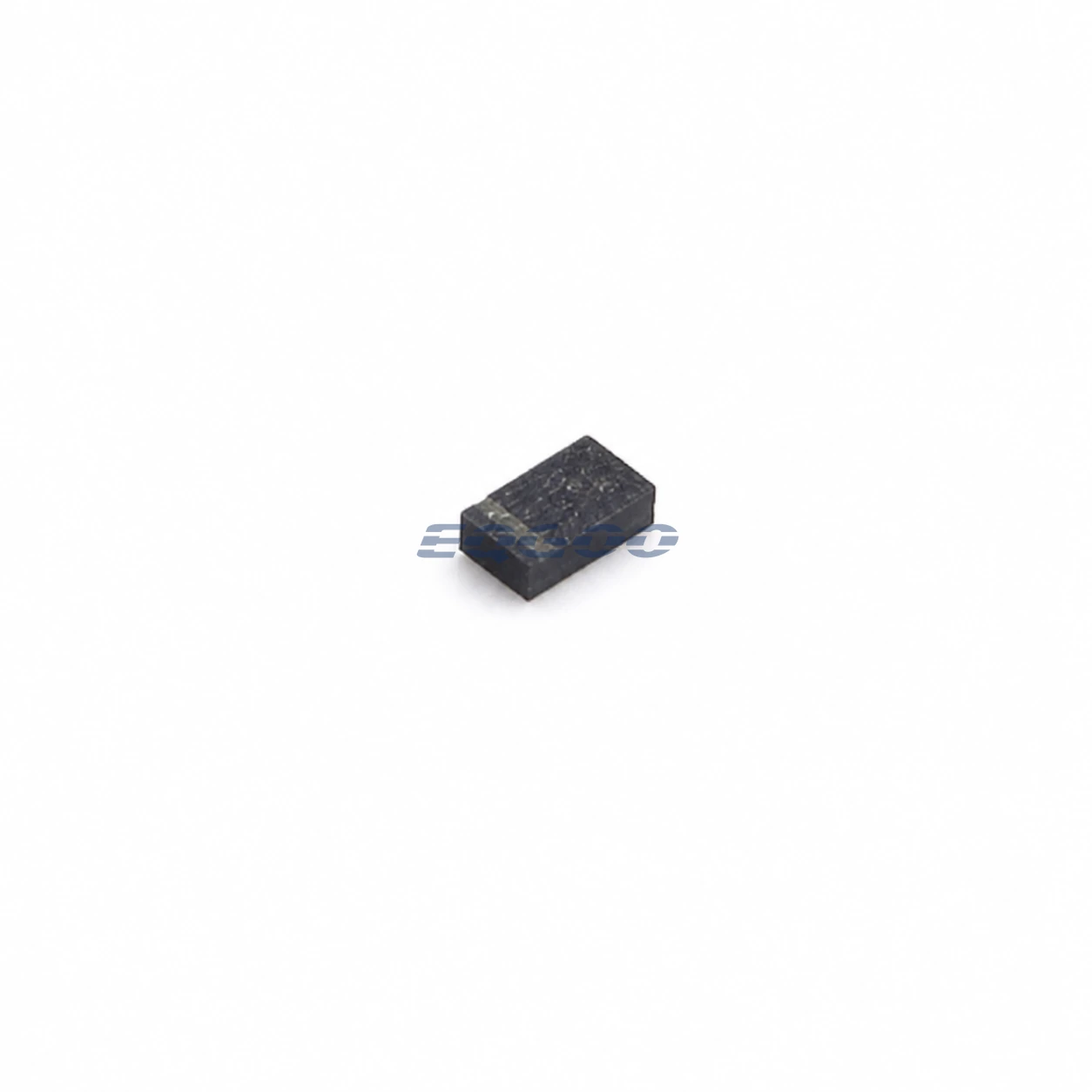
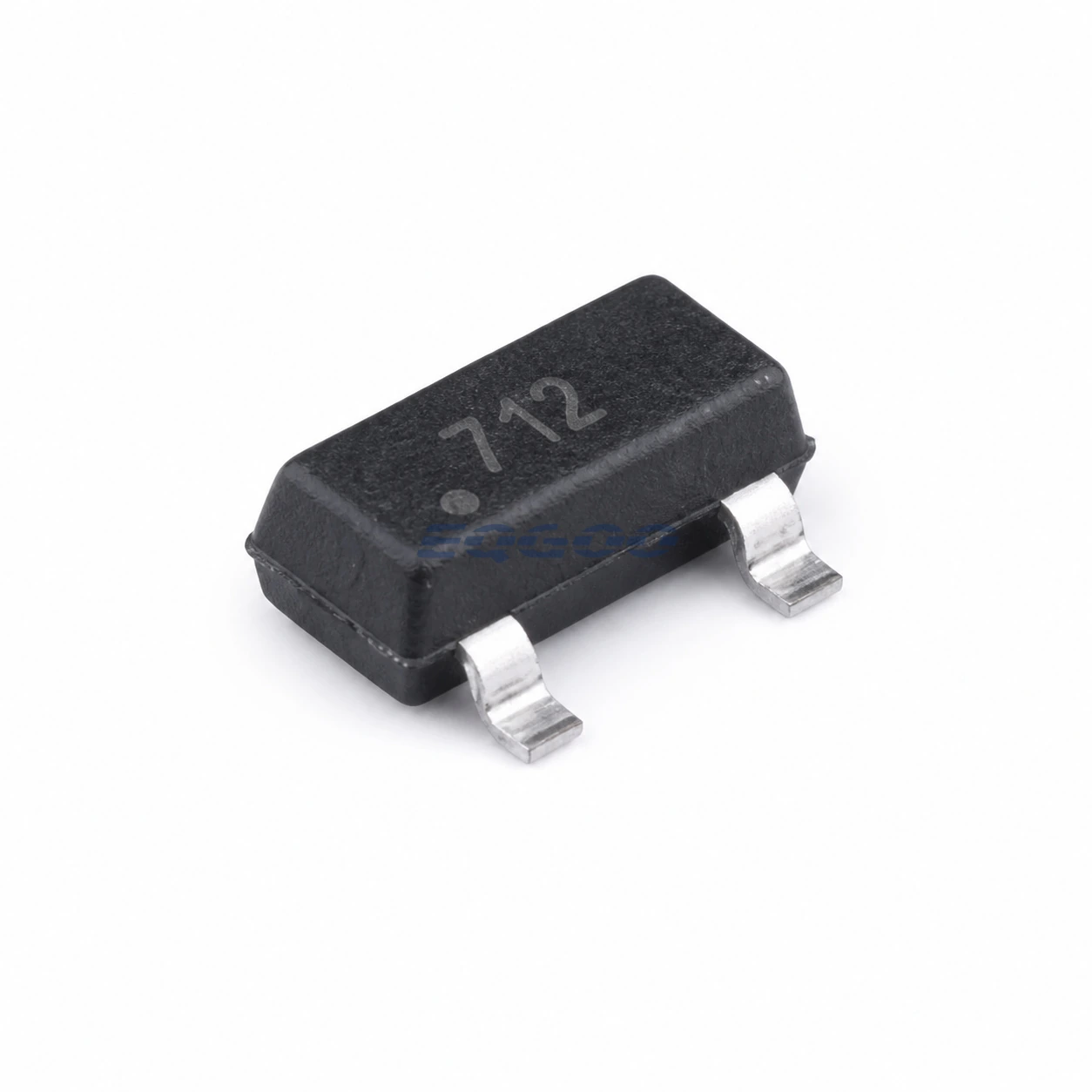
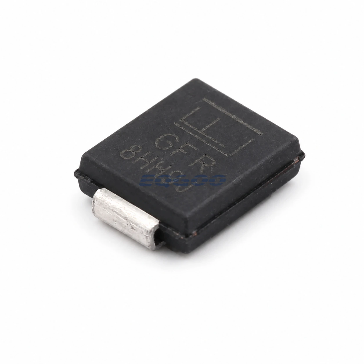
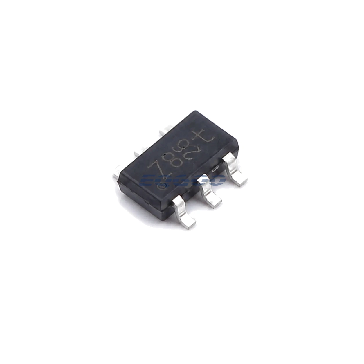
Designed as a quadruple bidirectional ESD transient-voltage suppressor, Nexperia BZA408B,115 uses the SOT-457 package. For substitution or design review, the strongest comparison points are Device Function (quadruple bidirectional ESD transient-voltage suppressor), Protected Lines (4), Esd Rating (>15 kV).
Selection-Critical Data
| Parameter | Confirmed Data | Why It Matters |
|---|---|---|
| Device Function | quadruple bidirectional ESD transient-voltage suppressor | Defines the device function or architecture that a compatible replacement must preserve before secondary ratings are compared. |
| Protected Lines | 4 | Defines how many signal or power lines can be protected by one device and therefore the channel-count fit in the board design. |
| Esd Rating | >15 kV (IEC1000-4-2) | Defines the stated electrostatic-discharge withstand level and therefore the protection margin available at the protected interface. |
| Non Clamping Range | -5 to +5 V | Defines the qualified measurement or environmental range that the design must remain within. |
| Channel Separation | >70 dB | Defines the number or arrangement of parallel signal/control paths and therefore the resources a replacement must provide. |
| Diode Capacitance | <75 pF | Loads the protected signal line and therefore affects high-frequency bandwidth, edge rate and signal integrity. |
| Exact Package | SOT-457 | Determines PCB footprint, pinout, mechanical assembly and orderable-variant compatibility. |
Power-Device Selection Notes
quadruple bidirectional ESD transient-voltage suppressor is the stated device function value. Defines the device function or architecture that a compatible replacement must preserve before secondary ratings are compared.
At SOT-457, the exact package determines PCB footprint, pinout, mechanical assembly and orderable-variant compatibility.
The protected lines is 4; this defines how many signal or power lines can be protected by one device and therefore the channel-count fit in the board design. The esd rating is >15 kV; this defines the stated electrostatic-discharge withstand level and therefore the protection margin available at the protected interface. Technical condition: IEC1000-4-2.
At -5 to +5 V, the non clamping range defines the qualified measurement or environmental range that the design must remain within. Channel Separation is >70 dB. Defines the number or arrangement of parallel signal/control paths and therefore the resources a replacement must provide.
For diode capacitance, <75 pF is the approved value. Loads the protected signal line and therefore affects high-frequency bandwidth, edge rate and signal integrity.