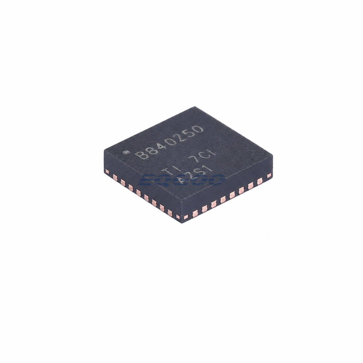

Key Selection Information
| Selection Parameter | Confirmed Information |
|---|---|
| Battery Configuration | 1S to 4S Li-Ion / Li-Polymer pack |
| Gauging Method | Impedance Track technology |
| Pack Management | Integrated gauging, protection, authentication and cell balancing |
| FET Architecture | High-side N-channel protection FET drive |
| Cell Balancing | Internal balancing during charging or at rest; external balancing supported |
| Host Interface | SMBus v1.1 |
| Performance / Security | TURBO BOOST support, SHA-1 authentication, lifetime data logging |
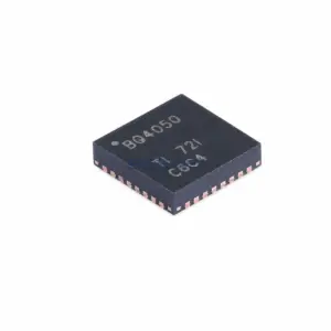
| Exact Package / Packing | VQFN (RSM), 32 pins, 4 mm × 4 mm; 3000-piece large tape and reel |
Product Overview
BQ40Z50RSMR-R1 is a 1S-to-4S smart-battery pack manager built around TI’s Impedance Track gauging technology. It combines capacity estimation, high-side protection-FET control, cell balancing, SMBus reporting, authentication and extensive safety logic in one 32-pin device.
Its most important distinction from BQ4050 is the gauging architecture. BQ40Z50 uses Impedance Track rather than CEDV, so the device continually models battery impedance and capacity behavior to compensate for aging, temperature and load-rate effects. That changes the chemistry-learning and production-configuration workflow even when the external pack hardware looks similar.
The R1 product also supports TI’s TURBO BOOST functionality for systems that use battery information to manage short high-power operating periods. This capability only becomes useful when the host, pack parameters and current/voltage limits are configured consistently; it should not be treated as an automatic increase in safe pack power.
For related devices, see HKEQGOO’s Battery Management category.
Technical Specifications
| Parameter | Verified Information |
|---|---|
| Manufacturer | Texas Instruments |
| Exact MPN | BQ40Z50RSMR-R1 |
| Cell Count | 1 to 4 series cells |
| Fuel-Gauge Algorithm | Impedance Track |
| Chemistry | Li-Ion / Li-Polymer; current TI product data also lists LiFePO4 support |
| Protection | Programmable voltage, current, temperature, timeout, FET and AFE protections |
| Cell Balancing | Internal balancing while charging or at rest; external balancing option |
| Internal Balancing Current | Up to approximately 10 mA stated in family datasheet |
| Host Interface | SMBus v1.1 |
| Authentication | SHA-1 |
| Diagnostics | Lifetime data monitor and black-box event logging |
| Performance Feature | TURBO BOOST mode support |
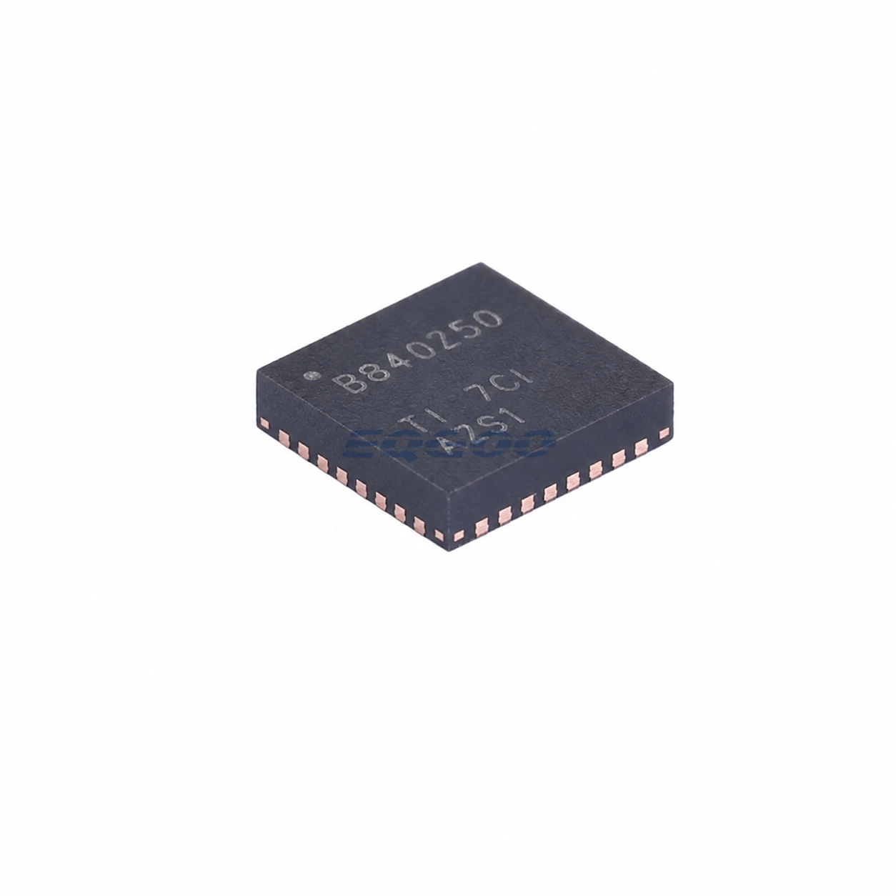
| Package | VQFN (RSM), 32 pins, 4 mm × 4 mm |
| Manufacturer Status | Active / Production |
| Part Marking | BQ40Z50 |
Functional Highlights
Impedance Track makes chemistry characterization part of product setup
BQ40Z50 does more than integrate current over time. The Impedance Track model uses measured cell behavior to update available capacity as the pack ages and operating conditions change. Correct chemistry identification, learning-cycle procedure and data-flash configuration are therefore part of production readiness, not optional tuning after the pack is assembled.
Balancing can operate while charging or while the pack is at rest
The internal bypass can balance multiple cells with modest current, while an external balancing circuit can be used when faster correction is required. Rest-mode balancing can be useful when the pack spends long periods connected but not charging, yet it also consumes energy and should be configured around the actual storage/use pattern.
TURBO BOOST depends on the pack’s real power limits
TURBO BOOST exposes battery capability information for systems that temporarily increase performance. The safe benefit depends on cell impedance, temperature, state of charge, FET/current-path limits, and host policy. The feature should be validated using the finished pack rather than interpreted as a fixed extra-current rating from the IC.
Design Considerations
- Complete the Impedance Track chemistry and learning workflow for the production cell. A correct schematic does not substitute for correct gauge characterization.
- Size balancing around capacity and expected imbalance. Internal balancing is convenient but low current; larger packs may need an external path.
- Coordinate pack protection with FET and fuse ratings. Primary protection, permanent-failure logic and external hardware must use compatible thresholds.
- Validate TURBO BOOST with actual cells and current paths. Peak-power decisions should include temperature, SOC, impedance, connector and FET losses.
- Treat authentication and data-flash programming as manufacturing operations. Security and protection depend on correctly provisioned devices.
Product Status and Exact Order Code
Manufacturer status: Active / Production
Texas Instruments lists BQ40Z50RSMR-R1 as an Active / Production 32-pin VQFN RSM device supplied in a 3000-piece large tape-and-reel carrier with Level-1-260C-UNLIM MSL classification, an operating-temperature listing of −40°C to +85°C, and part marking BQ40Z50. The -R1 suffix is part of the exact orderable identity and should be retained in purchasing records.
Related Engineering Resources
Quality & Verification Support
Third-party inspection or testing can be arranged according to customer requirements. Testing fees are borne by the buyer. Additional verification requirements can be discussed before shipment. After an order is placed, physical product, label, packaging, and Date Code photos may be provided where appropriate.
Request a Quote
To request a quotation, provide the manufacturer part number, required quantity, destination, target Date Code if applicable, and any testing or inspection requirements.