PoE PD classification plus isolated flyback control
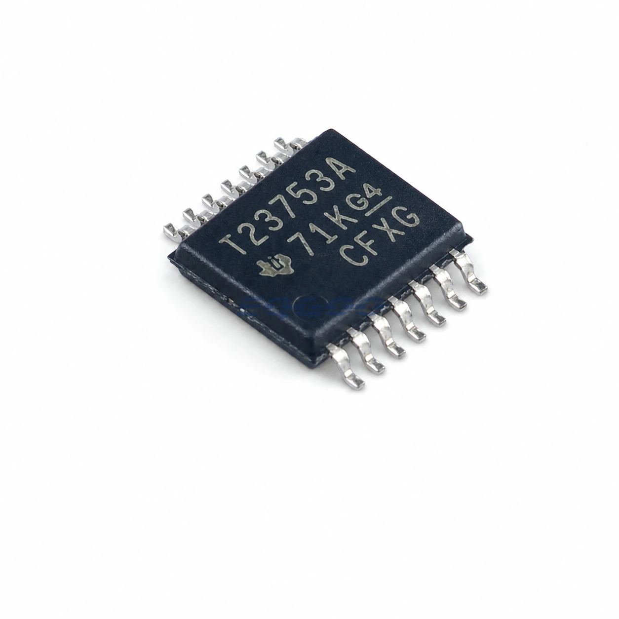
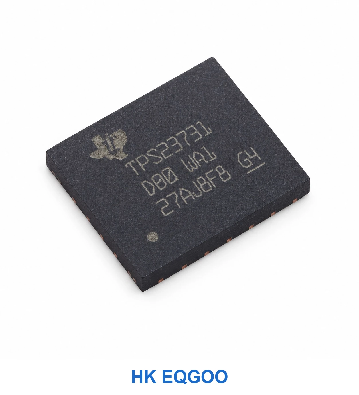
TPS23731RMTR is a Power over Ethernet powered-device interface and flyback DC/DC controller in a 45-contact RMT VQFN package. It is intended for isolated PoE endpoints such as network cameras, access points and IP telephones. Unlike a simple PoE detection front end, the device contains both powered-device classification functionality and a primary-side-regulation controller, but it still requires transformer, switching magnetics and output components. The distinction between an IEEE PoE input power allocation and the usable regulated secondary-side output power is essential when deciding whether this exact part fits an application.
PoE allocation, MPS and flyback regulation
The TI source specifies IEEE 802.3bt Type 3 Class 1–4 and IEEE 802.3at support, with an integrated 100 V hotswap MOSFET, automatic Maintain Power Signature and flyback control. The source’s up-to-30 W operating class is not permission to claim 30 W at the load in all cable or efficiency conditions. Primary-side regulation can remove an optocoupler in the reference topology, but it still depends on accurate transformer turns ratio and auxiliary-winding sampling. Adjustable frequency dithering, startup/soft-stop features and current-mode control must be evaluated alongside EMI filtering, thermal dissipation and IEEE classification timing.
Transformer topology and PD-controller selection
A proper alternative assessment verifies PoE classification range, hotswap FET current limit, MPS behavior, presence or absence of optocoupler feedback, sync-FET choices and the precise 45-pad RMT pin map. Many PoE controllers support the standard yet use different external power-stage topologies. To request TPS23731RMTR, specify the exact RMT suffix, network power budget, transformer arrangement, output voltage/current, isolation and cabling assumptions. Generic alternative lists are not guarantees of drop-in compatibility.
TPS23731RMTR PoE and power-stage considerations
| Selection parameter | TI-listed selection figure | Design implication / limit |
|---|---|---|
| Poe | IEEE 802.3bt Type 3 (Class 1-4) | PoE PD class describes input classification, not guaranteed load power |
| Fet | 100-V, 0.3-Ω (typ) Hotswap MOSFET | 100 V hotswap FET rating; 0.3 Ω is typical, not a Vin specification |
| Power | up to 30-W operation | 30 W operating class is not 30 W regulated output in every topology |
| Primary side | primary-side regulation | Auxiliary-winding feedback and transformer design determine PSR accuracy |
| Dither | Programmable frequency dithering for EMI | Frequency dithering is an EMI design tool, not EMC compliance by itself |
| Mps | Automatic Maintain Power Signature (MPS) | MPS depends on PSE type and load-current behavior |
| Temp | –40°C to 125°C junction temperature range | Junction rating; distinguish from permissible ambient temperature |
| Catalog package | VQFN-45(7×5) | RMT 45-pad, 7 × 5 mm; review thermal pad and isolation layout |
Quote TPS23731RMTR with the required power topology
Specify TPS23731RMTR, quantity, PoE class, output rail and flyback transformer strategy. Input classification and usable output power must be verified for the complete design.