Device Overview
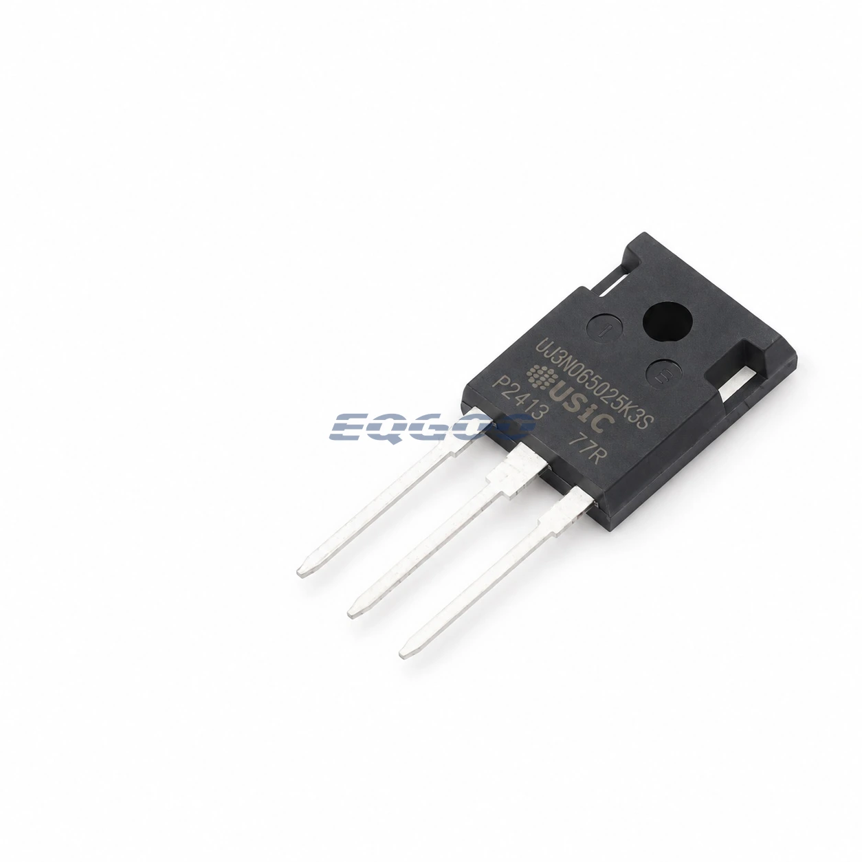
UJ3N065025K3S is a 650 V normally-on silicon-carbide JFET in a TO-247-3L package. The normally-on characteristic is fundamental to how this device should be evaluated: it conducts at VGS = 0 V, so it should not be treated as a drop-in equivalent to a normally-off MOSFET solely because the voltage class and package look similar.
For this exact part, the datasheet gives 25 mOhm typical RDS(on) at VGS = 0 V, ID = 20 A and TJ = 25 °C. The same device is characterized with 240 nC typical total gate charge under VDS = 400 V, ID = 60 A and VGS swept from -18 V to 0 V.
Selection-Critical Specifications
| Parameter | Confirmed Information | Conditions / Notes |
|---|---|---|
| Device type | Normally-on SiC JFET | Conducting characteristic at VGS = 0 V |
| Drain-source voltage | 650 V | |
| RDS(on), typical | 25 mOhm | VGS = 0 V, ID = 20 A, TJ = 25 °C |
| Total gate charge, typical | 240 nC | VDS = 400 V, ID = 60 A, VGS = -18 V to 0 V |
| Junction-to-case thermal resistance | 0.26 °C/W typ, 0.34 °C/W max | |
| Maximum junction temperature | 175 °C | |
| Package | TO-247-3L | Exact package |
Gate-Drive and Thermal Considerations
The negative gate-bias range used for the gate-charge characterization is an important integration detail. A replacement review should therefore compare gate-drive behavior as well as RDS(on), not just the 650 V rating.
The 25 mOhm RDS(on), 240 nC gate charge and junction-to-case thermal resistance describe different parts of the conduction, switching and thermal trade-off. They should be considered together, especially when comparing another TO-247 power device that uses a different semiconductor technology or gate-drive convention.
The TO-247-3L package also fixes the mechanical form factor for board and heatsink integration. Matching the package alone does not establish electrical or gate-drive equivalence.
Engineering Resource
For a higher on-resistance 650 V normally-on SiC JFET option in TO-247-3L, compare UJ3N065080K3S (80 mΩ typical at the manufacturer test conditions) with this UJ3N065025K3S (25 mΩ typical). Qorvo’s SiC selector lists different current capability as well; this power-device choice affects conduction loss and thermal design. Both are normally-on JFETs, not drop-in replacements for normally-off MOSFETs.