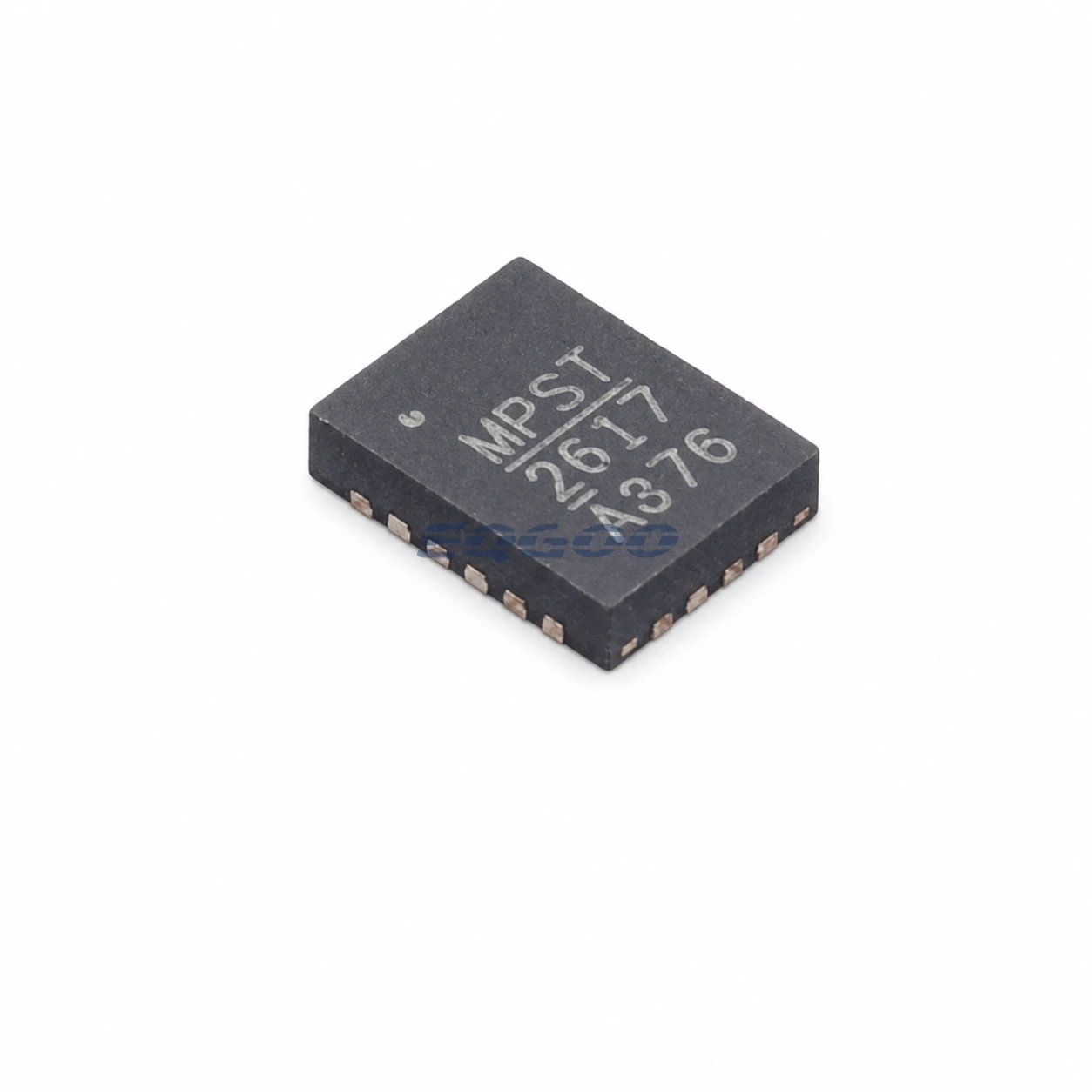
Device Overview
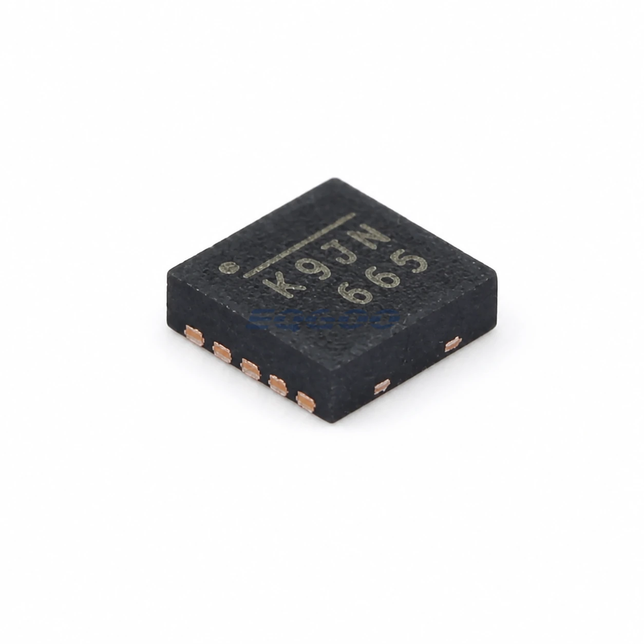
Designed as a single-cell switch-mode battery charger with NVDC power-path management, MPS MP2617AGL-Z uses the QFN-20 package. The main engineering checks for this variant are Device Function (single-cell switch-mode battery charger with NVDC power-path management), Input Voltage (4 to 10 V), Charge Current (up to 3 A).
Selection-Critical Data
| Parameter | Confirmed Data | Why It Matters |
|---|---|---|
| Device Function | single-cell switch-mode battery charger with NVDC power-path management | Defines the device function or architecture that a compatible replacement must preserve before secondary ratings are compared. |
| Input Voltage | 4 to 10 V | Defines compatibility with the available system input rail and its operating range. |
| Charge Current | up to 3 A | Defines the current-handling or drive capability that must meet the load while respecting current-path and thermal limits. |
| Battery Charge Voltage | 4.35 V (single-cell Li+) | Defines the output/reference voltage range or setpoint that must match the target rail, battery or threshold. |
| Switching Frequency | 1.6 MHz | Defines the converter or clock switching rate and affects timing, passive-component selection, losses and EMI; it is not an RF operating band. |
| Exact Package | QFN-20 | Determines PCB footprint, pinout, mechanical assembly and orderable-variant compatibility. |
Power-Management Selection Notes
For device function, single-cell switch-mode battery charger with NVDC power-path management is the approved value. Defines the device function or architecture that a compatible replacement must preserve before secondary ratings are compared. 4 to 10 V is the stated input voltage value. Defines compatibility with the available system input rail and its operating range. The charge current is up to 3 A; this defines the current-handling or drive capability that must meet the load while respecting current-path and thermal limits.
The switching frequency is 1.6 MHz; this defines the operating frequency or RF band that must cover the intended signal frequencies.
For exact package, QFN-20 is the approved value. Determines PCB footprint, pinout, mechanical assembly and orderable-variant compatibility.
The battery charge voltage is 4.35 V; this defines the output/reference voltage range or setpoint that must match the target rail, battery or threshold. Technical condition: single-cell Li+.