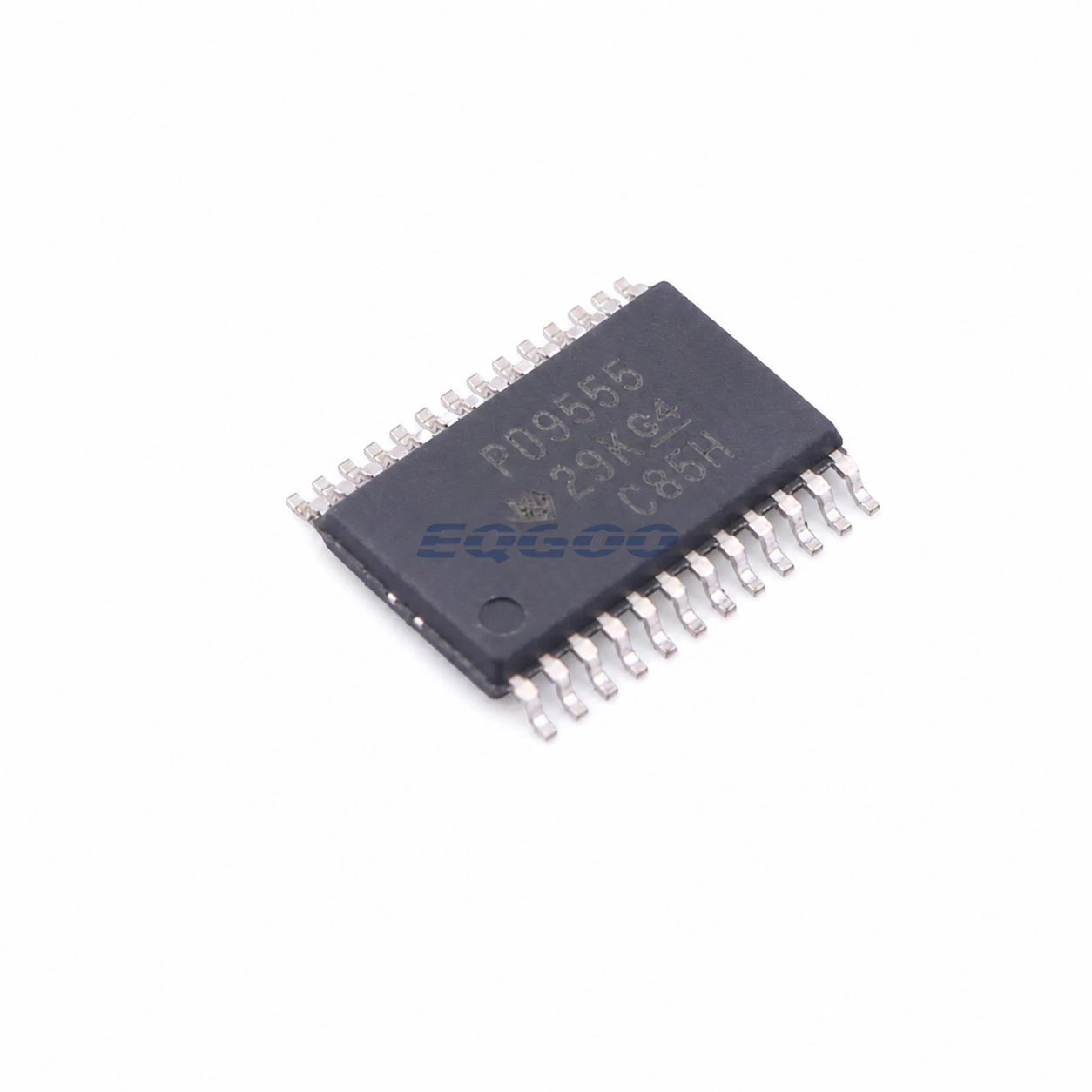

Key Selection Information
| Selection Parameter | Confirmed Information |
|---|---|
| GPIO | 16 configurable I/O pins in two 8-bit banks |
| Supply | 2.3 V to 5.5 V |
| Bus | I²C/SMBus up to 400 kHz |
| Addressing | 3 hardware address pins; up to 8 devices per bus |
| Interrupt | Open-drain active-low INT for input changes |
| Registers | Input, output, polarity inversion and configuration registers |
| Startup | All I/O default to inputs at power-up |
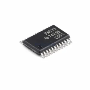
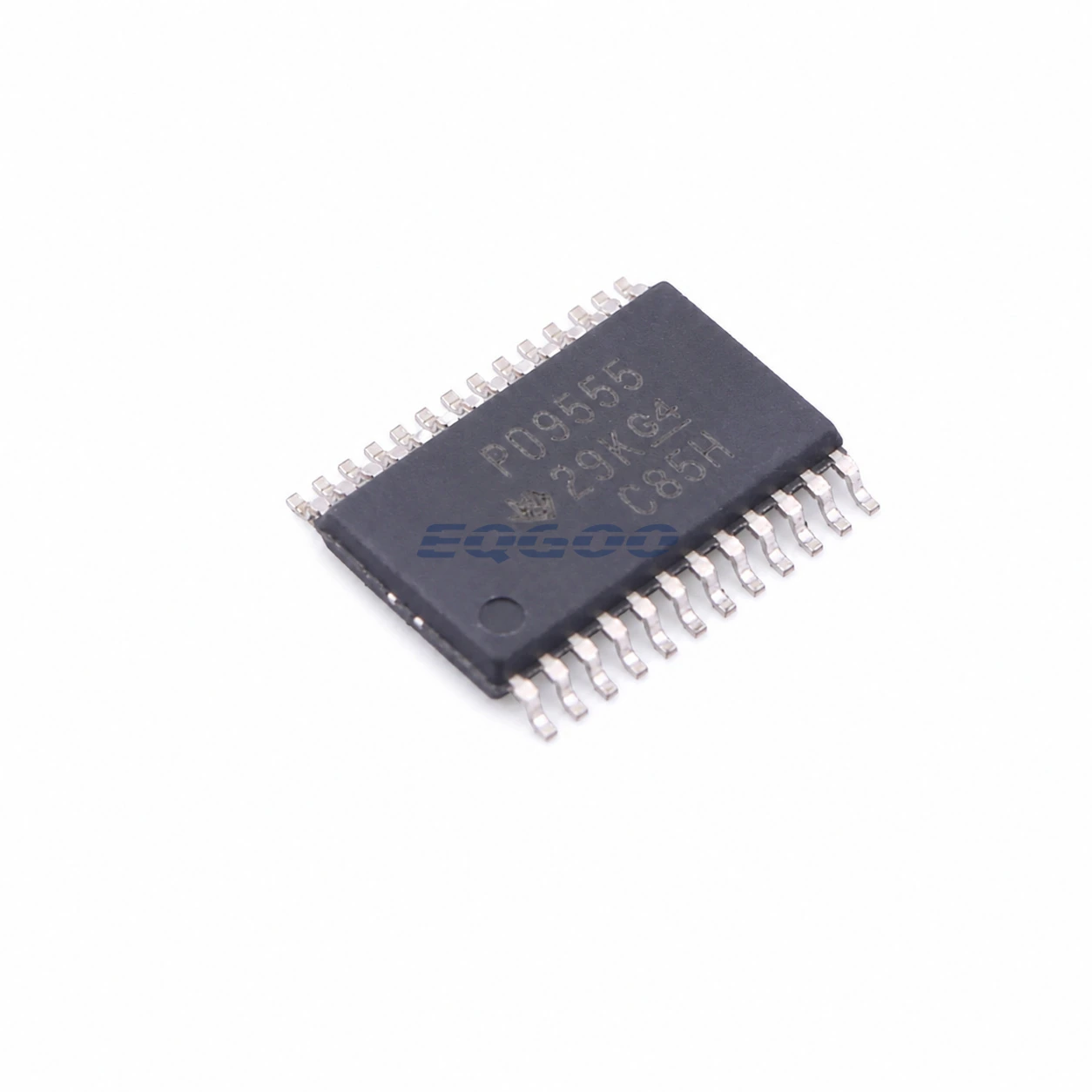
| Exact Package / Packing | TSSOP (PW), 24 pins; 2000-piece large tape and reel |
Product Overview
PCA9555PWR adds 16 general-purpose I/O lines to a processor over a 400-kHz I²C/SMBus connection. Two 8-bit register banks control direction, output state and polarity while INT allows input changes to wake the host instead of relying only on polling.
Its 2.3 V minimum VCC is an important compatibility boundary. Later TCA-family expanders in this batch support lower-voltage operation down to 1.65 V, so a design migrating to a lower logic rail should not assume PCA9555 remains suitable solely because the register model is familiar.
Three address pins allow eight PCA9555 devices on one bus. The PWR order code is the active TSSOP-24 large-reel format and keeps a leaded package that is easy to inspect/rework.
For related devices, see HKEQGOO’s I/O Expanders category.
Technical Specifications
| Parameter | Verified Information |
|---|---|
| Manufacturer | Texas Instruments |
| Exact MPN | PCA9555PWR |
| GPIO | 16 configurable I/O pins in two 8-bit banks |
| Supply | 2.3 V to 5.5 V |
| Bus | I²C/SMBus up to 400 kHz |
| Addressing | 3 hardware address pins; up to 8 devices per bus |
| Interrupt | Open-drain active-low INT for input changes |
| Registers | Input, output, polarity inversion and configuration registers |
| Startup | All I/O default to inputs at power-up |
| Exact Package / Packing | TSSOP (PW), 24 pins; 2000-piece large tape and reel |
| Manufacturer Status | Active / Production |
| Part Marking | PCA9555 family marking per TI addendum |
Functional Highlights
Interrupt-driven input expansion reduces I²C traffic
INT is asserted when an input differs from its previous state, allowing firmware to read ports only when something changes. The interrupt remains a shared summary signal, so software must read the affected registers to determine the source.
Power-up as inputs avoids unintended drive but requires initialization discipline
External loads may float until firmware writes output values/directions. Pull resistors or peripheral defaults should establish safe states before the expander is configured.
Design Considerations
- Confirm the 2.3 V minimum supply against the actual processor/board rail before reusing a low-voltage I/O-expander design.
- Set output data before changing a pin to output if external hardware must avoid a transition during initialization.
- Size SDA/SCL/INT pull-ups for bus capacitance and all devices on the shared voltage domain.
Product Status and Exact Order Code
Manufacturer status: Active / Production
Texas Instruments lists PCA9555PWR as Active / Production; TSSOP (PW), 24 pins; 2000-piece large tape and reel; −40°C to +85°C.
Related Engineering Resources
Quality & Verification Support
Third-party inspection or testing can be arranged according to customer requirements. Testing fees are borne by the buyer. Additional verification requirements can be discussed before shipment. After an order is placed, physical product, label, packaging, and Date Code photos may be provided where appropriate.
Request a Quote
To request a quotation, provide the manufacturer part number, required quantity, destination, target Date Code if applicable, and any testing or inspection requirements.