
Key Selection Information
| Selection Parameter | Confirmed Information |
|---|---|
| Loop Function | 2-wire 4–20 mA transmitter |
| Sensor Excitation | Two precision 800 µA current sources |
| Linearization | RTD second-order linearization circuitry |
| Sensors | 2-wire/3-wire RTD and bridge/instrumentation inputs |
| Supply | 7.5 V to 36 V loop supply |
| Precision | 0.4 µV/°C offset drift stated feature |
| Compatibility | Designed for industrial field transmitter / HART-compatible loop use |
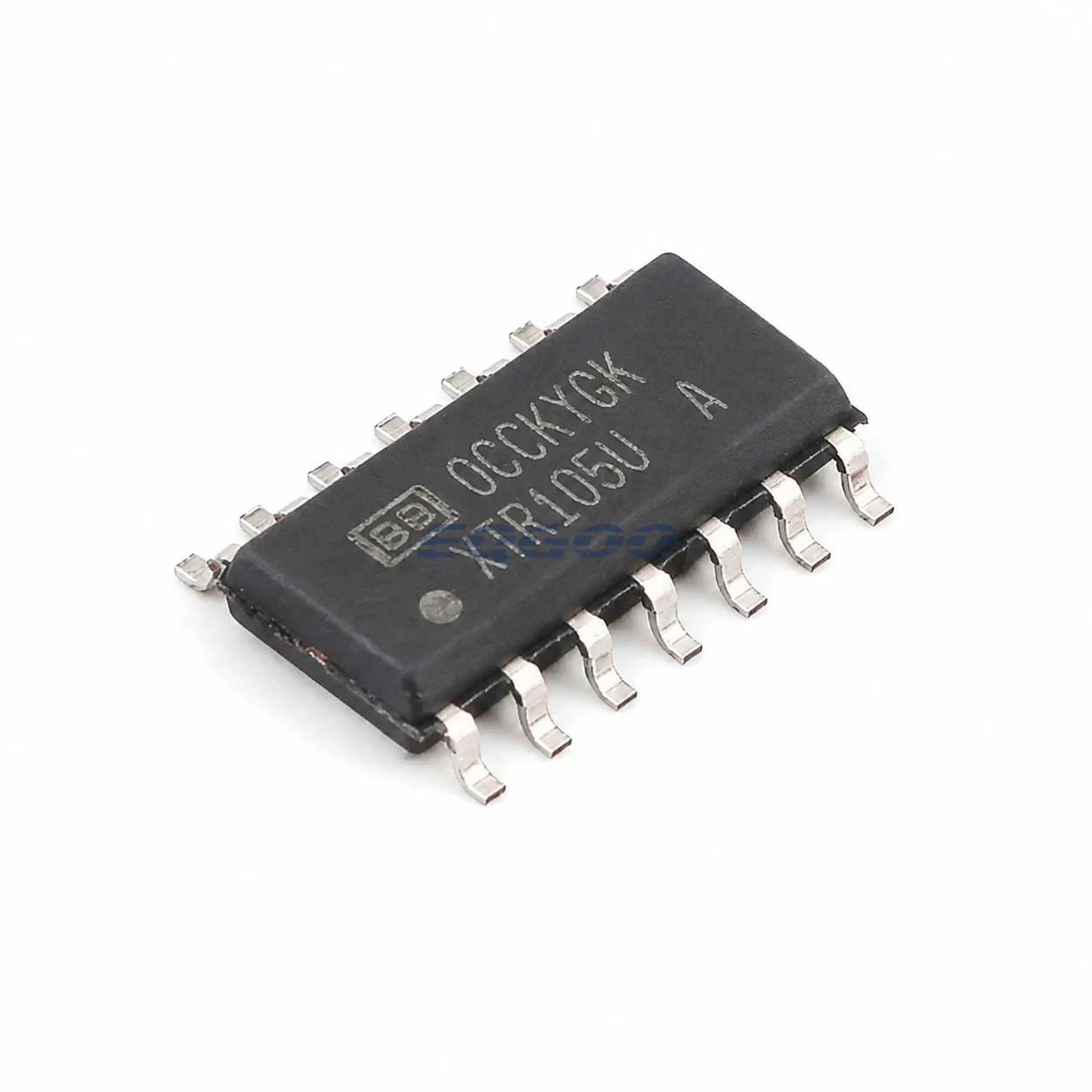
| Exact Package / Packing | SOIC (D), 14 pins; 2500-piece large tape and reel |
Product Overview
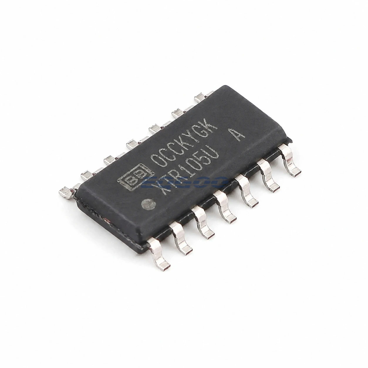
XTR105UA/2K5 integrates the major analog blocks needed to turn an RTD or bridge signal into a two-wire 4–20 mA current loop. Two matched 800 µA sources can excite RTDs, while the internal instrumentation amplifier and linearization network reduce the external precision-component count.
Its RTD linearization circuit can provide second-order correction, but resistor selection and sensor type remain application-specific. A 100 Ω Pt RTD span, for example, needs a different zero/span/linearization network from a pressure bridge.
The /2K5 code is the active 2500-piece reel SOIC-14 option. TI’s nomenclature also notes dual approved die-manufacturing sources for this exact order code, so incoming marking/die-source expectations should follow TI documentation rather than assuming a single fabrication source.
For related devices, see HKEQGOO’s ADCs/DACs – Special Purpose category.
Technical Specifications
| Parameter | Verified Information |
|---|---|
| Manufacturer | Texas Instruments |
| Exact MPN | XTR105UA/2K5 |
| Loop Function | 2-wire 4–20 mA transmitter |
| Sensor Excitation | Two precision 800 µA current sources |
| Linearization | RTD second-order linearization circuitry |
| Sensors | 2-wire/3-wire RTD and bridge/instrumentation inputs |
| Supply | 7.5 V to 36 V loop supply |
| Precision | 0.4 µV/°C offset drift stated feature |
| Compatibility | Designed for industrial field transmitter / HART-compatible loop use |
| Exact Package / Packing | SOIC (D), 14 pins; 2500-piece large tape and reel |
| Manufacturer Status | Active / Production |
| Part Marking | XTR105U / XTR105UA family marking per TI addendum |
Functional Highlights
Integrated excitation makes RTD wiring part of the measurement architecture
In a 3-wire RTD, lead-resistance cancellation depends on current matching and resistor/wiring symmetry. Sensor wiring errors can exceed the IC drift if the field connection is not designed carefully.
Loop headroom limits how much circuitry can be powered
The transmitter must operate from the loop voltage while leaving enough compliance for cable, receiver resistor and protection. Any HART modem or sensor electronics powered from the loop consume the same voltage/current budget.
Design Considerations
- Calculate zero/span/linearization resistors from the exact RTD/bridge range rather than copying a reference design blindly.
- Include cable and receiver voltage drop in the minimum loop-supply headroom calculation.
- Use matched low-drift resistors where they set gain/linearization; the IC cannot correct external ratio drift.
Product Status and Exact Order Code
Manufacturer status: Active / Production
Texas Instruments lists XTR105UA/2K5 as Active / Production; SOIC (D), 14 pins; 2500-piece large tape and reel; Level-3-260C-168 HR; −40°C to +85°C; exact order code XTR105UA/2K5.
Related Engineering Resources
Quality & Verification Support
Third-party inspection or testing can be arranged according to customer requirements. Testing fees are borne by the buyer. Additional verification requirements can be discussed before shipment. After an order is placed, physical product, label, packaging, and Date Code photos may be provided where appropriate.
Request a Quote
To request a quotation, provide the manufacturer part number, required quantity, destination, target Date Code if applicable, and any testing or inspection requirements.